Add touch sensors which trigger audio tags. This helps visually impaired people find their way around a new device. Or you could make an educational toy to help Junior learn what things are called. Or you could add a warning to ‘keep off’ your stuff! Or….

YouTube player

Please note: I copied and modified the Android code from one of the examples in Simon Monk’s book “Arduino + Android for the Evil Genius” to get this all going.

Project Steps

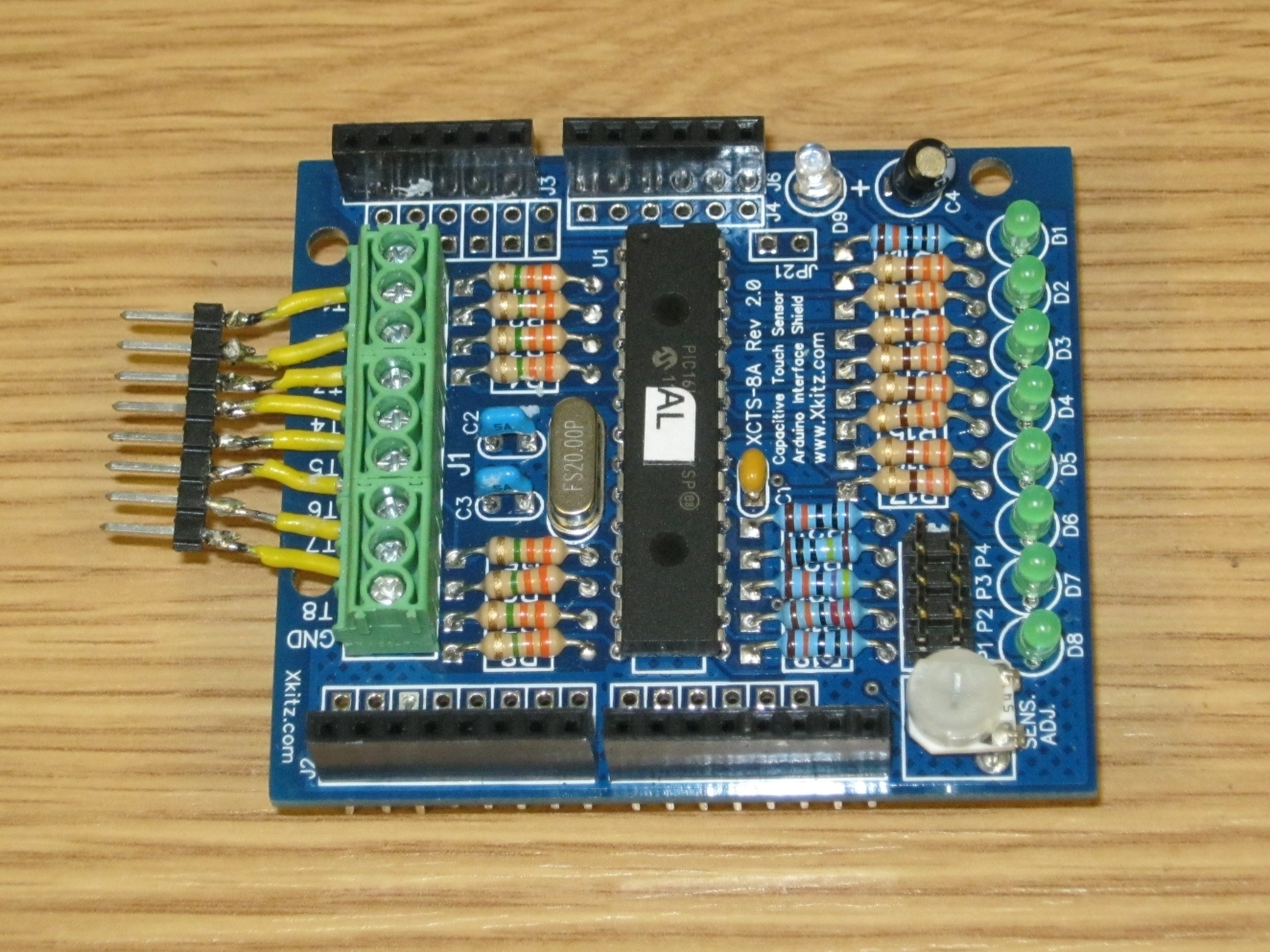
Solder up your Xkitz touch sensor board(s), following the instructions that come with them. Blue-tack is a great help for keeping components in place while you turn the board over to solder them. Each board can handle 8 channels. Set a unique address for each board by using a jumper on the header pins P1 to P4. For this project I used two boards to give a total of 16 touch sensors. I left one board with no jumper and placed a jumper across P2 on the other.

A jumper needs to be soldered across one of the communication ports to allow the Arduino to communicate with the boards. Use the same port for all of the boards. This is detailed in the Xkitz instructions. I use channel 2.

We will make the header pin attachment, with the yellow wires, in the next step. This will be used to attach the wires that connect with the controls that you are enhancing with touch sensors.

Strip short lengths of your single-core hookup wire and solder them to a strip of 8 x 0.1″ header pins. Only strip a smidgen of insulation off the end that you are soldering as the insulation will melt back a surprising amount. I find a blob of blue tack useful for holding the wire so that I don’t burn my fingers or cut through the insulation by using metal pliers. The wires need to be long enough so that they can fan out and connect to the green terminal block on the Xkitz board. You need one of these for each of your XKitz boards.

Solder stackable header pins to the USB Shield so that you can connect it to the Arduino and still be able to connect the XKitz boards on top. The order in which you finally stack the boards does not matter. Use blue-tack (again!) to keep the headers square while you flip over the board and solder the pins on the base of the board.

Here’s the full Arduino stack. In the photo I am using a battery shield, but you can also use an external power supply. Have you ever seen so many Arduino boards in a stack?

Load the ArduinoTouch sketch on to your Uno board. You can download the sketch file ArduinoTouch1.pde from the link at the bottom of my web page.

The green LEDs should light when you touch the header pins. You may need to adjust the sensitivity of the touch sensor channels by using the potentiometer on the XKitz boards.

Connect your Arduino Uno to the Arduino programming environment. Fire up the serial monitor and set the baud rate to 115200. You should see details of the Xkitz boards displayed. I gratuitously copied sections of the code from the XKitz demo sketch.

We need thin laminated wire loops or a coil on top of each control that you wish to sense. These wires should be routed through your device and will connect with your board stack – more of that in the next step.

Disassemble the device that you are enhancing so that you can get at both sides of the control panel. For rubber-membrane-style controls, you can sew the wire through as I did on the digital radio. For solid buttons, you can glue down a little circle of wire and drill a small hole to thread it through. I used small bits of sticky tape to secure the wires inside the case and made a small hole in the side to bring out the loose ends.

You need to bring out the ends of the wires from the side or back of your case so that they can be terminated to connect with the XKitz boards. I sealed up the little holes that I made using – what else – a little blue tack. Terminate the touch sensor wires by soldering them onto strips of 8 x 0.1″ header sockets. Each strip will connect to an Xkitz board.

Connect the touch sensor wire sockets onto the pins of the Xkitz boards. Test that touching your control triggers the touch sensor – the green LED should go on. You may need to adjust the sensitivity of the touch sensor by altering the potentiometer on the Xkitz board. You can also display the active channels using the ArduinoTouch1 sketch and the serial monitor.

For each channel, you need to make a sound file in 3GP format. Channel one is called channel_0.3gp, channel two channel_1.3gp and so on. These files need to go onto the SD card in your Android phone in the directory /TouchButtons.

Use any audio recording software with a microphone to create the audio files for your controls in WAV or MP3 format – most don’t support 3GP format directly. To convert these files to 3GP format, I use Free 3GP Converter, available here.

To interface the Arduino stack to an Android phone, we use a modified micro-USB cable. We need a 1K resistor in the power line (the red wire) to prevent the phone from trying to charge through the Arduino. Use a scalpel to strip off the insulation on the cable, cut out 5 or 6mm of the red wire, then solder in the 1K resistor. You can wrap up the assembly with insulation tape for a neater finish if you like.

Thanks to Simon Monk, author of “Android + Arduino for the Evil Genius” for details of how to do this.

Time to load the ArduinoTouch.apk app onto your Android phone. This can be found at the bottom of my web page.

To load the APK file onto your phone, Google for instructions. You will need to connect your phone to your PC using a micro-USB cable, or put the APK file onto your SD card and let the phone discover it.

Connect the phone to the stack of boards with your modified cable, connect the boards to your device and fire everything up! If you need extra volume, you can use an external speaker such as the X-mini.

Check out the video in the Introduction for what should happen. Check connections and power to the Arduino boards if it isn’t working as expected.