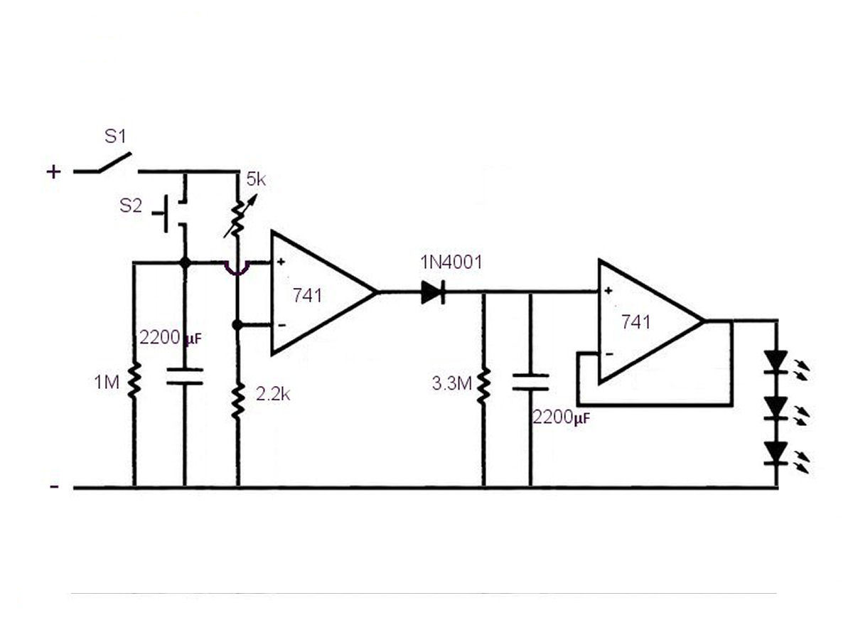
A lot of people find it easier to fall asleep with a dim light such as a nightlight in the room. But the down side of most nightlights is that they waste electricity because they are on all night when you really only need them to be on while you are falling asleep. So I designed a nightlight that will automatically dim and turn itself off.
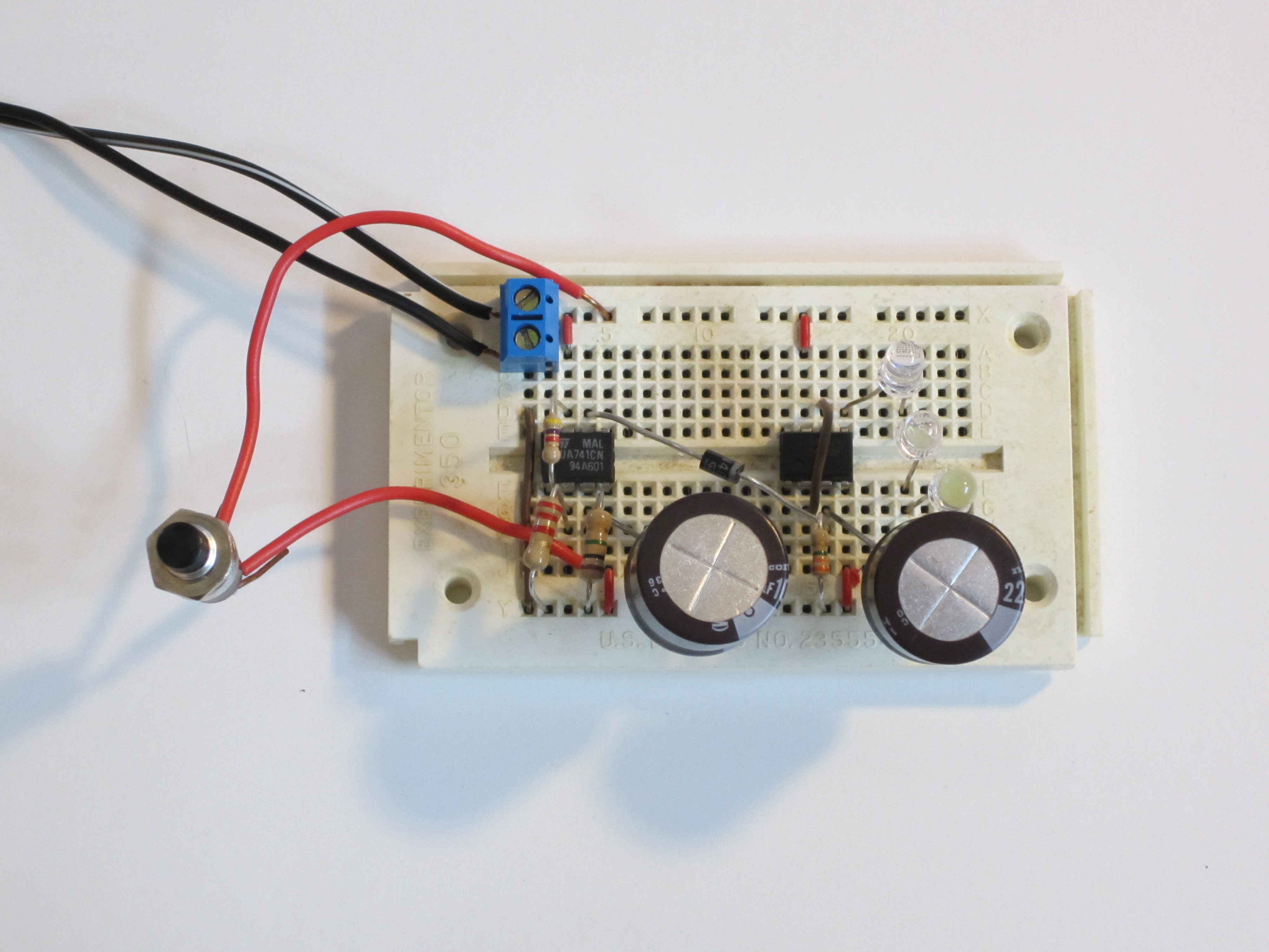
Here is a brief video of the build: