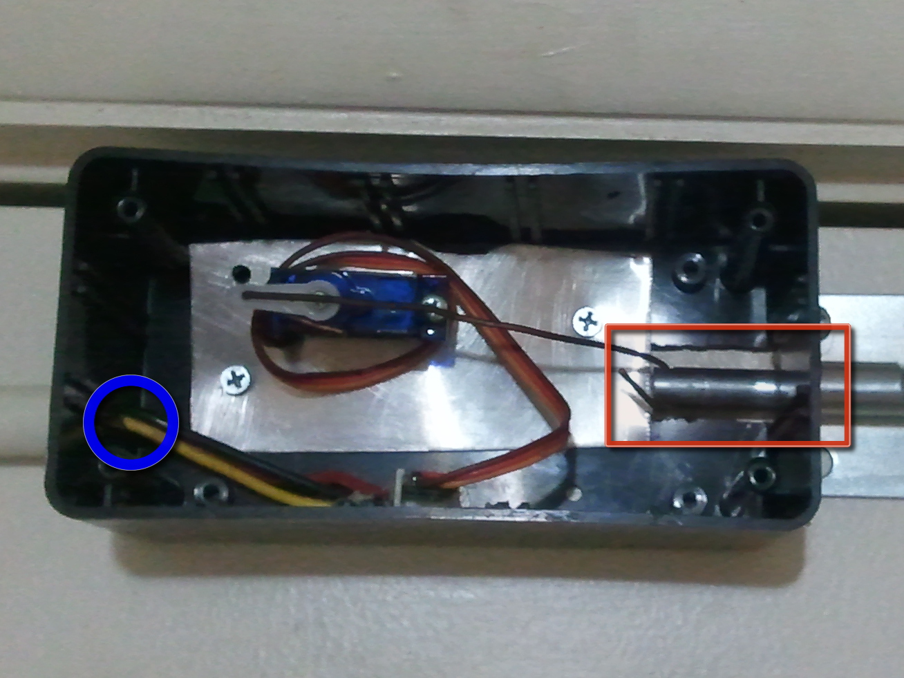
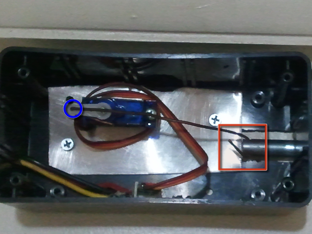
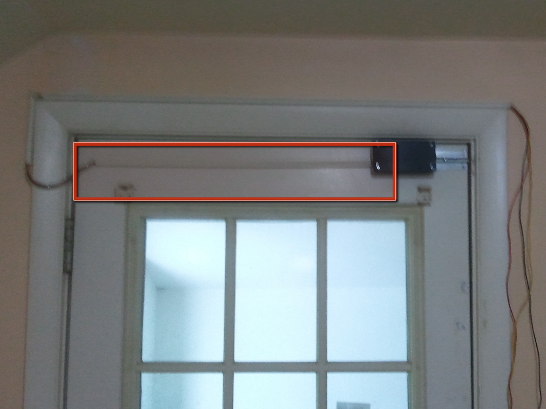
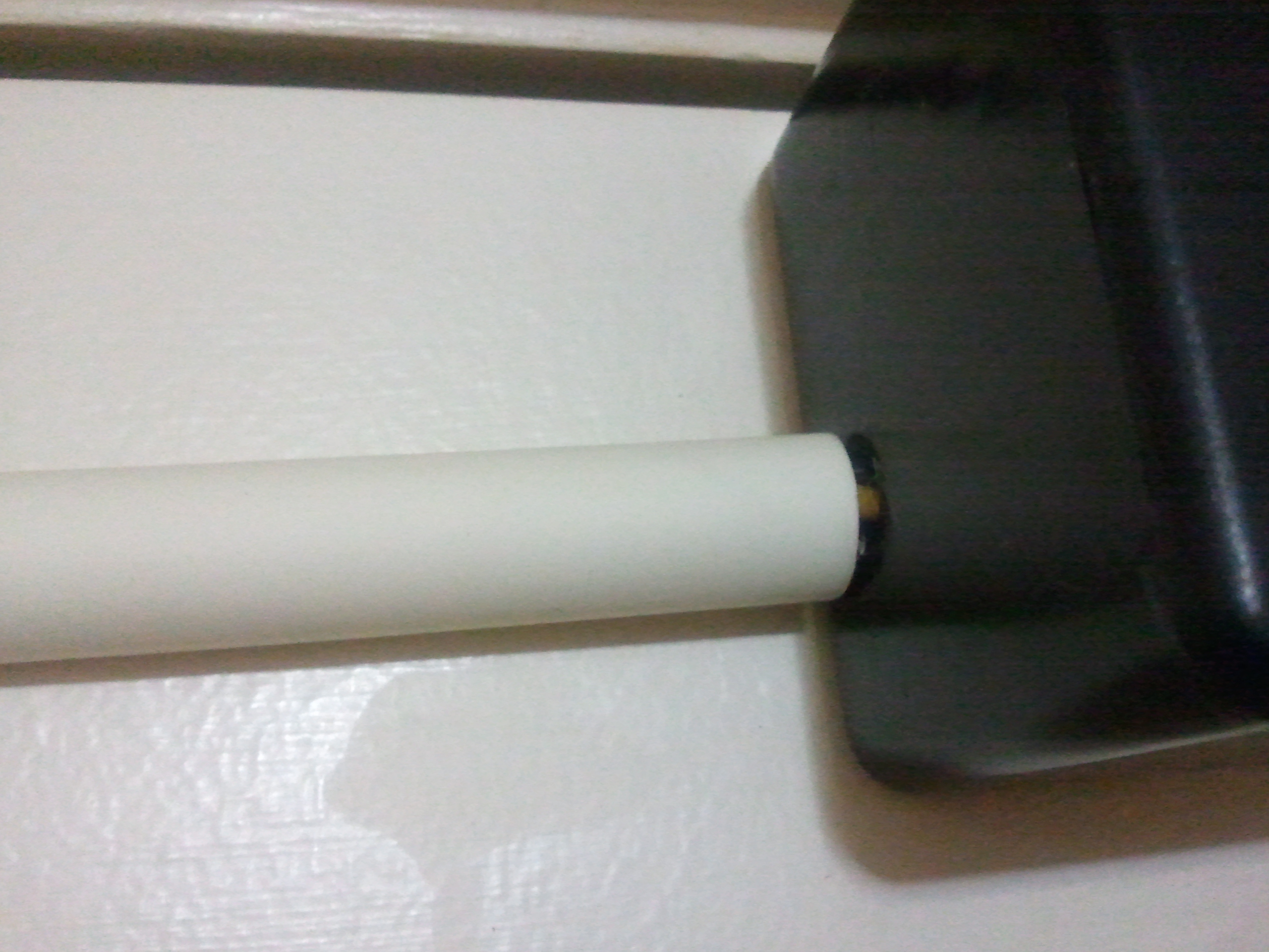
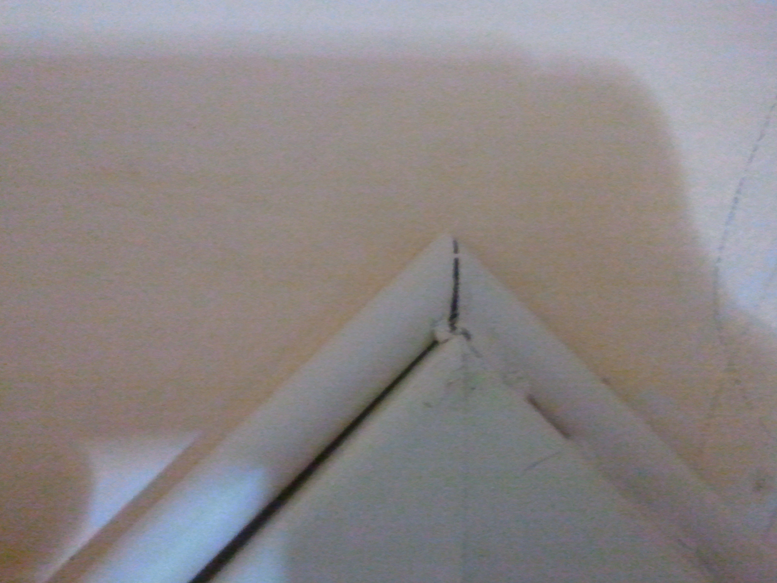
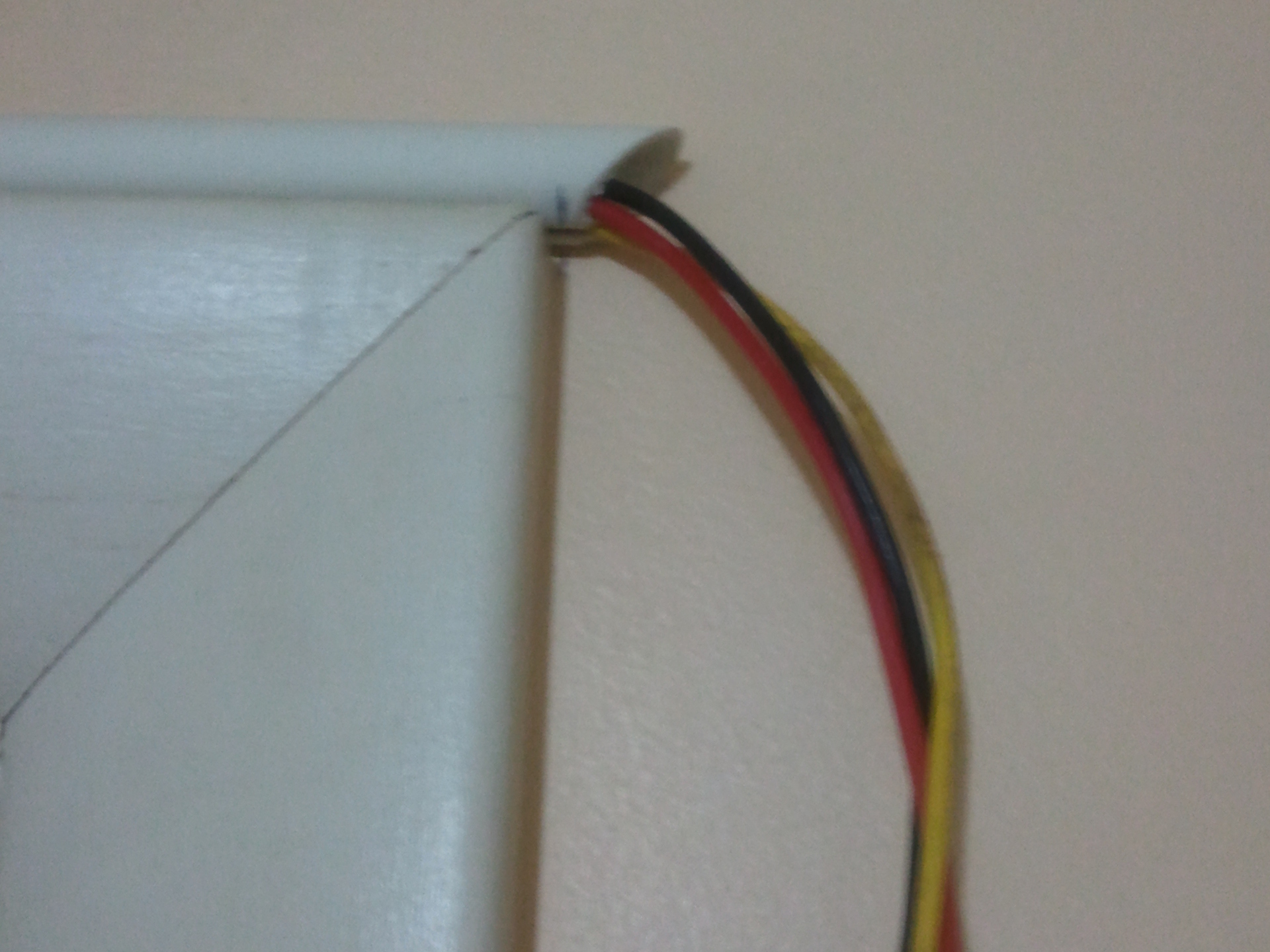
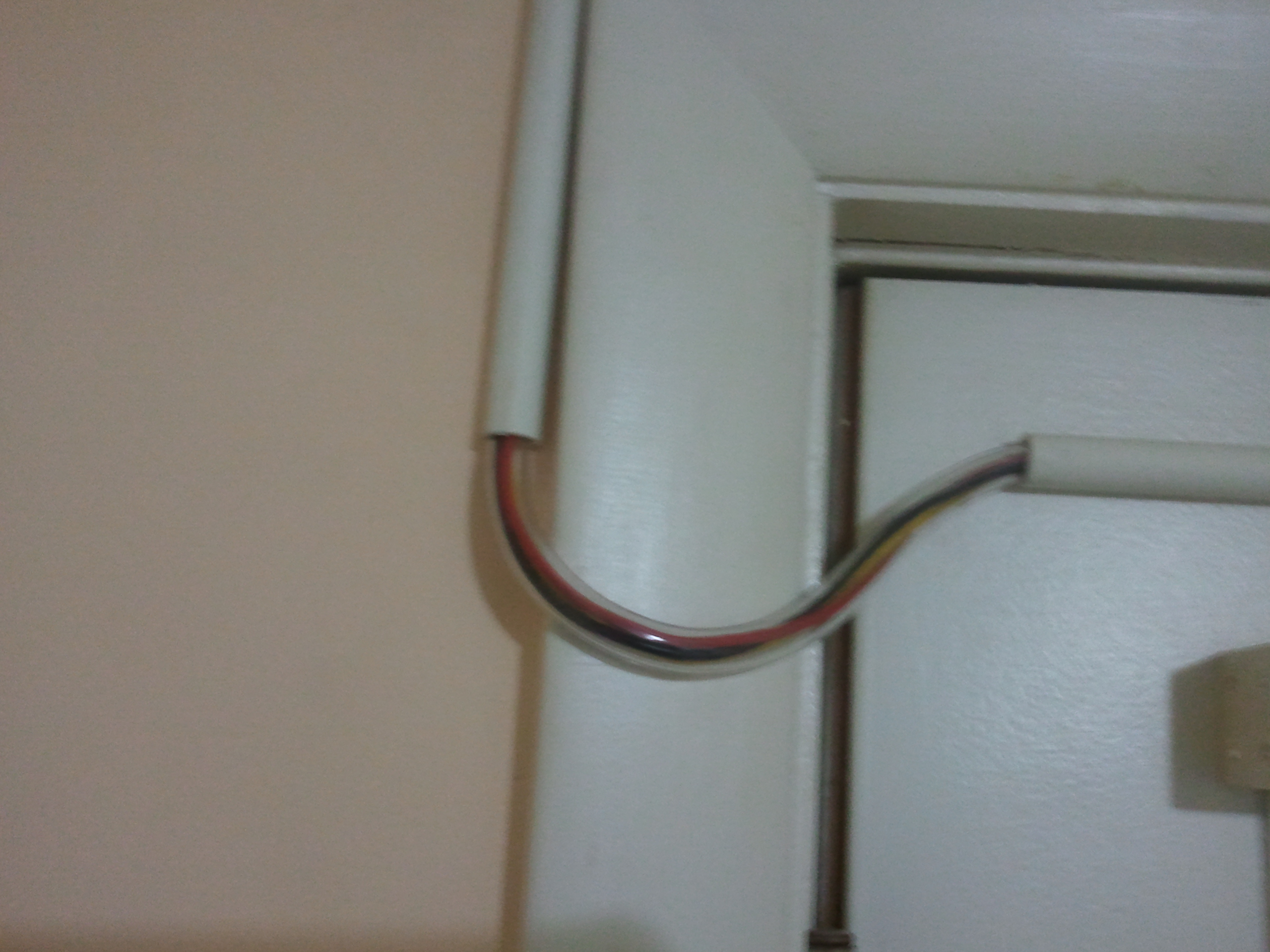
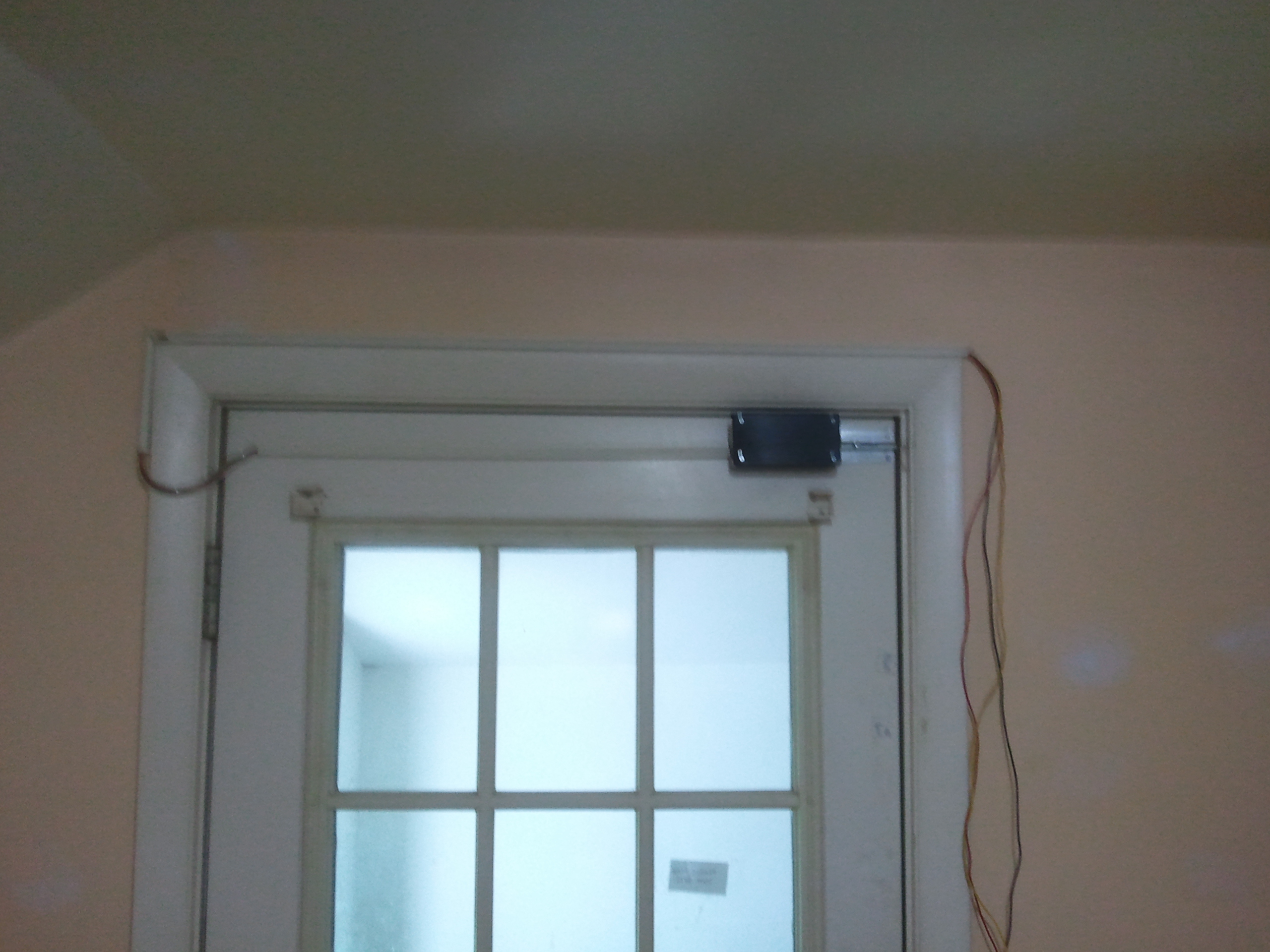
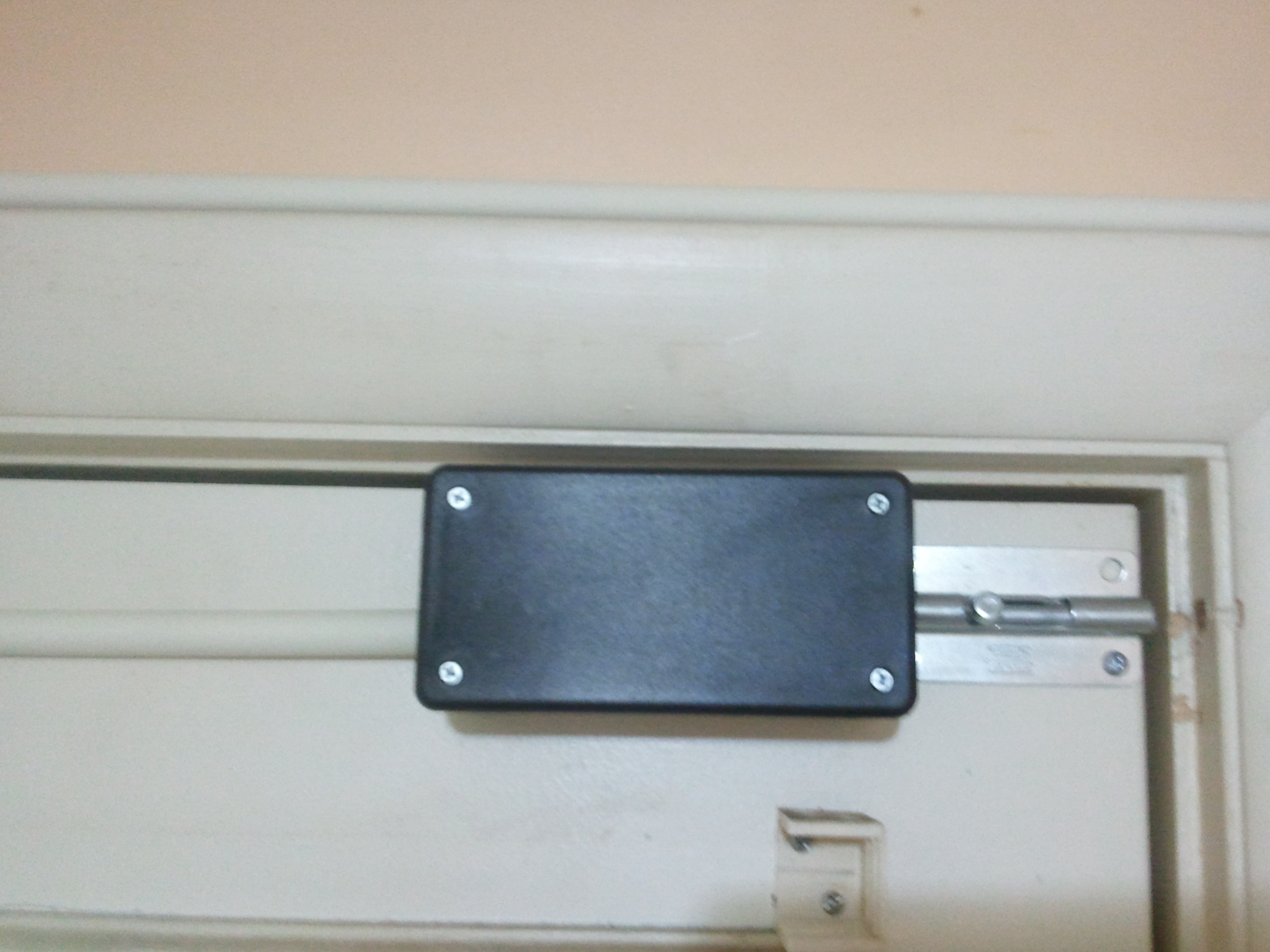
First I will show you how to make the enclosure, and route the wires. Then I will show you how to hook up the Servo & Arduino.
Projects from Make: Magazine
Automatic Door Lock/Unlock (For Home/Office)
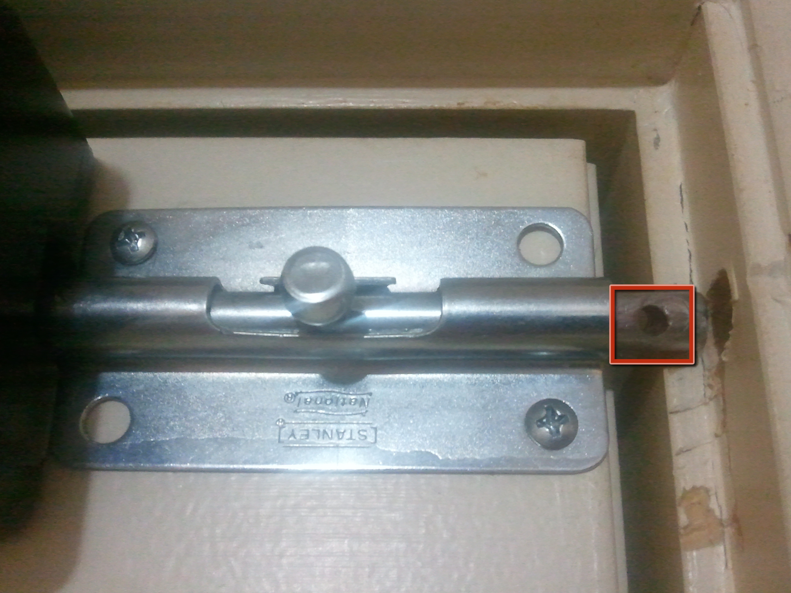
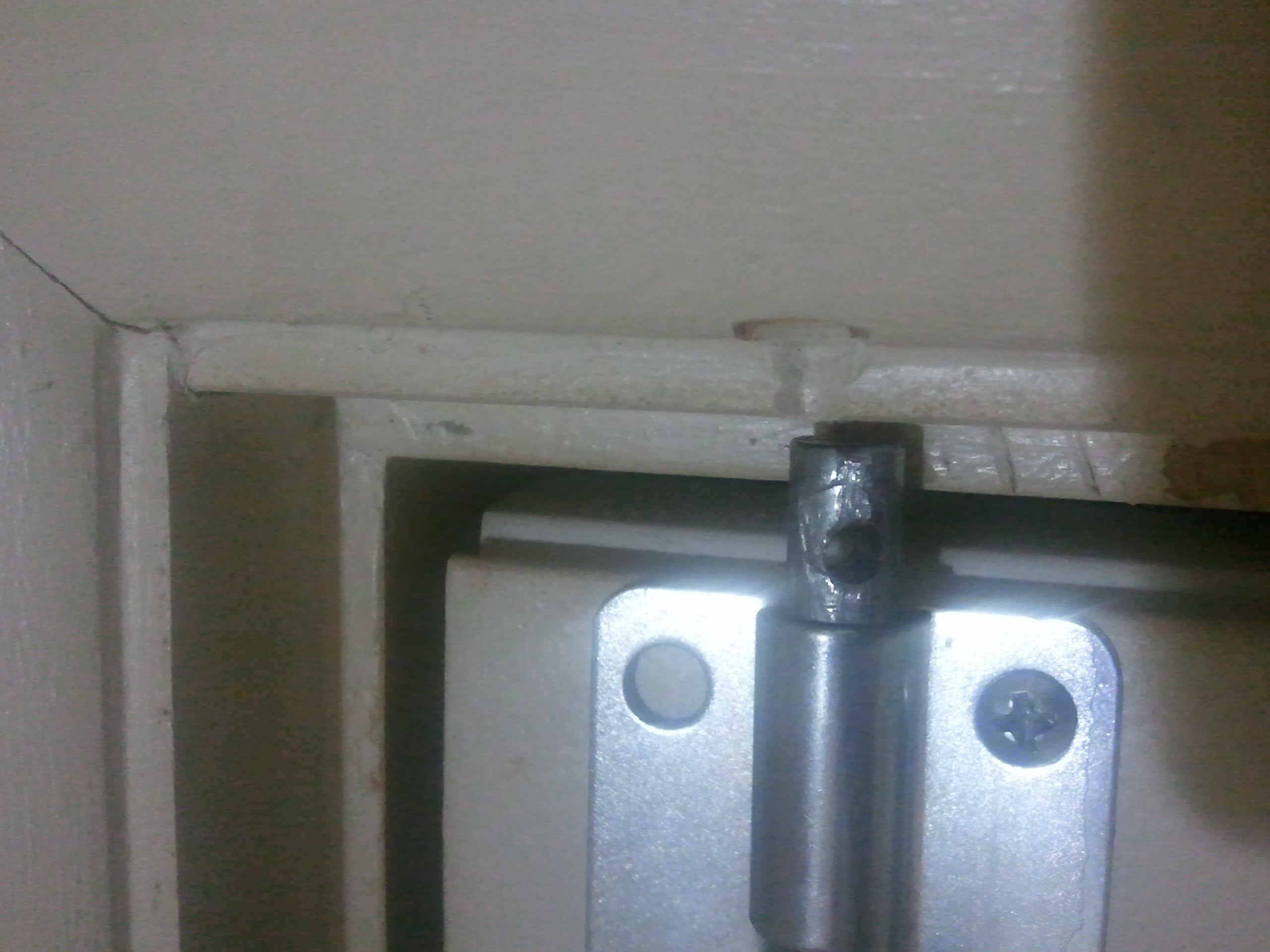
Here we are going to make a Automatic Door Lock/Unlock for your home/office. We will use a Servo, connected to a Lock by a wire. It will be controlled with a Arduino.
- By Sean Cherven
- Time Required: 2 - 4 Hours
- Print this Project
- Like
- Digg
- Del
- Tumblr
- VKontakte
- Flattr
- Buffer
- Love This
- Odnoklassniki
- Meneame
- Blogger
- Amazon
- Yahoo Mail
- Gmail
- AOL
- Newsvine
- HackerNews
- Evernote
- MySpace
- Mail.ru
- Viadeo
- Line
- Comments
- Yummly
- SMS
- Viber
- Telegram
- Subscribe
- Skype
- Facebook Messenger
- Kakao
- LiveJournal
- Yammer
- Edgar
- Fintel
- Mix
- Instapaper
- Copy Link
Parts
- Project wire (1)
- Slide Door Lock (1) Look in the pictures, I'm not sure what the actual name of them are.
- Project Enclosure (5x2.5x2') (1)
- Micro Servo 9g (1)
- Flexible Tubing (1) Make sure it fits snug in the end of the conduit.
- Conduit (1) I used a Plastic, Self-Adhesive type.
Tools
- Drill and drill bits
- Nibbler tool
Steps
Advertisement
- Using a Drill & Nibbler Tool, make a square hole in the Project Enclosure as shown in the picture (In the red box).
- You want it big enough so the sliding lock has enough room to move freely all the way into the project enclosure.
- Next, Drill a hole just big enough for the wires to go through (All 3 of them).
- You want this hole to be as close to the door as possible, so the conduit will line up with it.
- Don't make the mistake I did and drill the hole in the wrong end! The hole should go on the end that is INSIDE the enclosure.
- Drill a small hole through the end of the slide lock as shown.
- Try to get the hole as close to the end as possible!
- This is important because it needs that extra room to slide.
- Drill a hole in the servo gear just big enough for the wire to go through (Blue Circle in the picture).
- Mount the Servo inside the project box, and attach a strong wire (Coat Hanger?) to the servo and slide lock as shown in the picture.
- Don't Permanently mount it until you can test it out. (Alignment is the key)
- You can use a small dab of hot glue to mount it if you have nothing else.
- Using Project Wire, attach very long lengths of wire to the wires on the servo. (Be sure to connect all 3).
- Run the wires through the small hole in the project box that we drilled in step 1.
- Run a piece of conduit on the door itself, from the project box to the other end of the door.
- Next, Run the 3 wires through the conduit.
- Leave about 2" of space between the end of the conduit and the edge of the door.
- Be sure to align the conduit to the hole we drill in the project box.
- Now we're going to run the wires through the flexible tubing as shown.
- Next, slide the flexible tubing inside the ends of the Conduit as shown in the picture.
- You can use hot glue to hold the tubing inside the conduit if needed.
- What this tubing does, is allows the wires to flex when the door is opened and closed.
- Now that we have the conduit and wires all run, and the servo is attached the slide lock, we can hook up the wires!
- Attach the Power wire on the servo to the +5v on the Arduino.
- Attach the Ground wire from the servo to the GND on the Arduino.
- Attach the Signal wire from the Servo to Digital Pin 12.