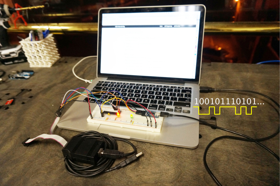
A microcontroller is a self-contained, but very limited computer — halfway between a computer and a component.
The top reasons to integrate a microcontroller into your projects are connectivity and interactivity, and one easy way to get your microcontroller talking with the outside world is standard asynchronous serial I/O. Many devices can communicate this way, from wi-fi routers to GPS units to your desktop or laptop computer. Getting comfortable with serial I/O makes debugging your AVR programs much easier because the AVR can finally talk to you, opening up a huge opportunity for awesome.
In this Skill Builder, we’ll set up two-way communication between an AVR microcontroller and your computer. Your computer will command the AVR to blink an LED, then the AVR will open a web page of your choice in a browser at the push of a breadboarded button using serial I/O.
You’ll need the following software:
- Project code Free download from makezine.com/go/avr-usart-serial, includes C code for the AVR, Python code, and a Makefile
- AVRDUDE and the AVR-GCC compiler Free downloads for:
- Mac: AVR CrossPack, obdev.at/products/crosspack/index.html
- Linux: Open terminal and type: sudo apt-get install avrdude avrdude-doc binutils-avr avr-libc gcc-avr
- Windows: WinAVR, sourceforge.net/projects/winavr/files/WinAVR. Select the option to add AVRDUDE to your path during the install.
- pySerial package from pypi.python.org/pypi/pyserial/2.7 for serial communication in Python
Asynchronous Serial Communications — A Quick Technical Overview
Computers like to talk to each other in binary: ones and zeros. A simple way to send these binary bits between devices is to connect them together with a wire, and let a high or low voltage on the wire denote a one or zero. Sending bits one at a time like this is serial communication because the bits are sent in series, one after the other.
For asynchronous serial communication (above), there is no common clock signal between the two devices, so to interpret a stream of voltages, each device needs to know how fast the bits are being sent: the baud rate.
Atmel’s megaAVR family of AVRs (the ATmega series) have a built-in universal synchronous and asynchronous serial receiver/transmitter (USART for short) hardware peripheral that takes care of all of the hard bits — setting and reading voltages on the serial communication lines at just the right times. Using the USART is not hard: We configure the baud rate, turn the transmitter and receiver sections on, and then feed it data. The USART hardware takes care of the rest.
Configuration
The AVR chips set the baud rate by taking the CPU clock and dividing it down to the right speed. Your main job, in configuring the chip, is to figure out the correct division factor.
The AVR USART hardware samples each bit multiple times to make sure that it’s reading a consistent voltage level. In particular, it has two modes: one where it samples 16 times per bit (“normal” mode) and another where it samples 8 times per bit (“double speed” mode). So you’re going to divide the CPU speed by 16 and 8 times the baud rate respectively, and then use that result to set the USART timing clock divider.
There are two more catches, though. First, you need to subtract 1 from the result. This is because the AVR’s counter starts counting with 0 rather than 1. So if you want the AVR to divide by 4, select 3 for the counter value: 0, 1, 2, 3.
The second catch is tricky, and this is why I think it’s worth doing the math by hand as follows at least once. (The AVR standard library includes utilities that help you set up the baud rate automatically.) The AVR only deals in whole numbers, but unless you’ve chosen your CPU speed to be a multiple of the baud rate, the result of the division above is unlikely to be a round number. So when you round this result off to fit in the AVR, you’re introducing some error in the baud rate. A little error is fine, but too much makes the serial communications unreliable.
Baud Rate Example
Say I’m running the CPU at full speed off the internal CPU clock — at 8MHz — and sampling the default 16 times per bit. Let’s see which of the standard baud rates work well:
8,000,000 / 16 / 9,600 = 52.08 = 0.2%
8,000,000 / 16 / 14,400 = 34.72 = 0.8%
8,000,000 / 16 / 19,200 = 26.04 = 0.2%
8,000,000 / 16 / 28,800 = 17.36 = 2.1%
8,000,000 / 16 / 38,400 = 13.02 = 0.2%
8,000,000 / 16 / 57,600 = 8.68 = 3.7%
There are a few things to notice here. First, 9,600 baud, 19,200 baud, and 38,400 baud all look pretty good — with the same 0.2% error. The 14,400 baud rate isn’t horrible, but around 1% error is pushing it. Rates of 28,800 and 57,600 baud may not work at all with this CPU speed and multiplier combo.

Mini Project — Blinking Web-Page-Loader Button
Now you’ll breadboard an AVR, program it with an ISP, and connect it via USB-serial so it can communicate with your computer and launch a web page.


