BEAM robot building techniques allow you to build fun and simple little robots with lots of room for stylizing. BEAM vibrobots use pager motors to move. We’ll use what’s known as a “solar engine” (Type 1 "FLED” variety), store bought or scavanged pager motors, and some paperclips. Let the build begin!
BEAM is a type of robot design that allows you to create little robot/robot-like critters and vehicles mainly using basic analog components (resistors, transistors, capacitors, diodes, LEDs). The challenge is to try and get as much robot-like behavior using these components. BEAM is an acronym for “Biology, Electronics, Aesthetics, Mechanics” and these four elements serve as inspiration in all BEAM design. You can find our more about BEAM on our BEAM robot page. You can find out more information on the FLED-type solar engine of the BEAM Wiki.
Project Steps
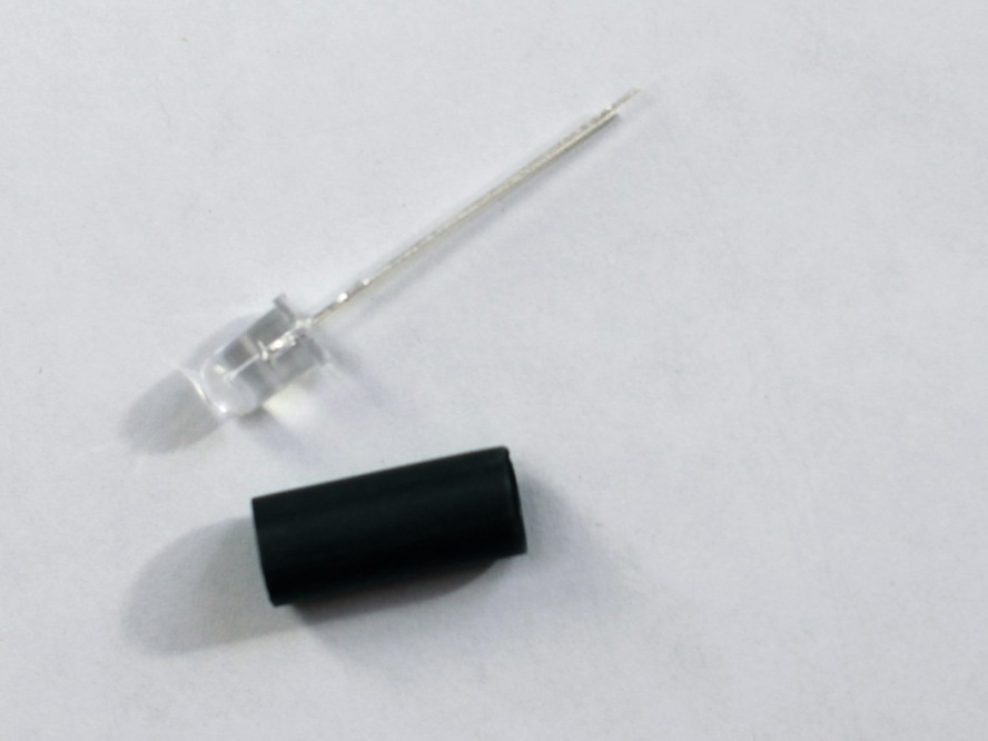
Preparing the LED
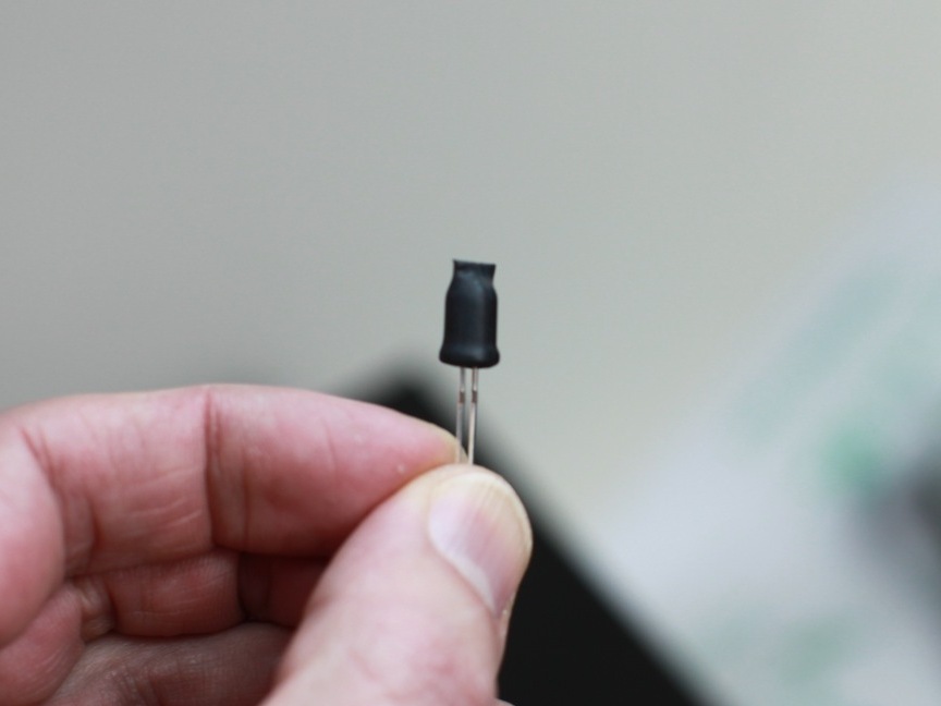
Cover the LED with some heat shrink tubing, tape, or opaque paint.
We’re not actually using the LED as a light, we’re using it as a conductor that will trigger the discharge phase of circuit.
To shrink the tubing, if you don’t have a heat-gun, you can use the tip of a soldering iron or a lighter. Hold the heat-source closer and closer to the tubing until it starts to shrink.
Be careful with your heat source and close in slowly until the material starts to shrink. Don’t melt it or set it (or you!) on fire.
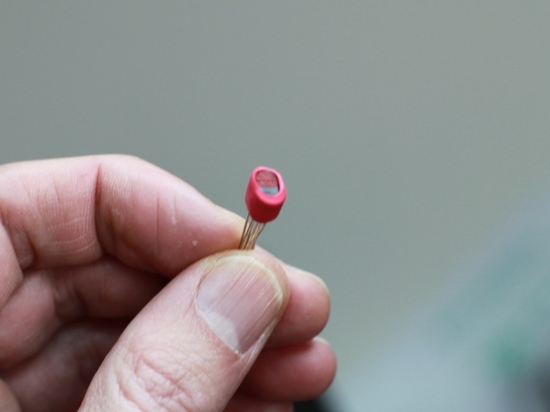
Preparing the Transistors
Paint the top of the 3906 transistor so you can identify the part later.
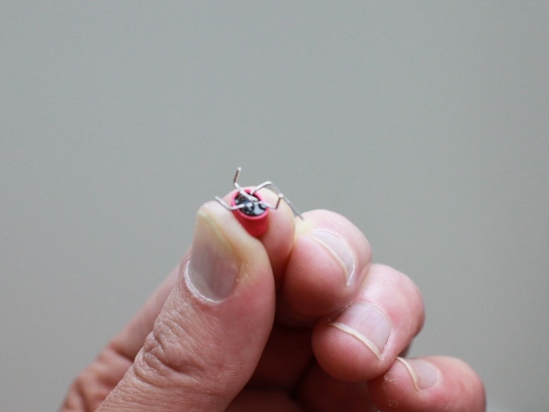
Glue the two transistors together with the flat parts of them facing each other.
Apply some heat shrink tubing around the transistors so you don’t have to wait for the glue to dry.
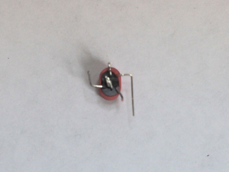
Flip the transistors over. Make sure to keep the 3906 on top.
Bend and trim the legs according to the images. The two touching leads should be soldered together.
Consult the illustration in Step 3 if you have trouble seeing how the transistor leads (legs) are connected.
Assembling a Solar Engine
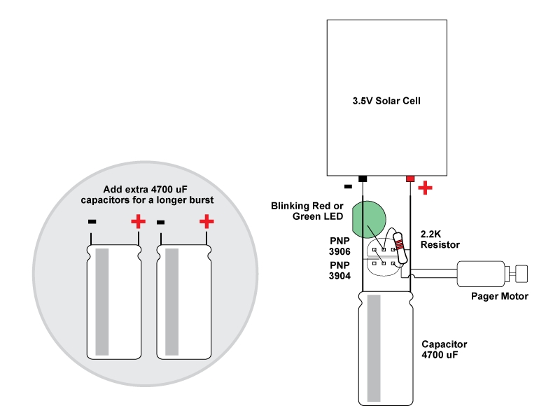
Solder on the LED. Make sure the negative lead (shorter leg) connects to the negative wire of the solar panel. Make sure the positive lead connects to the center lead on the 3906.
Solder on the 2.2KΩ resistor as indicated in the illustration. Unlike the LED, it is not polarity sensitive and it doesn’t matter what direction the resistor faces.
Solder on 4700uF capacitor.
Solder on the motor, as shown in the diagram.
Congratulate yourself. You now have a FLED-based BEAM solar engine built.
This solar engine is called a FLED-type to stands for “Flashing LED.” When the circuit has charged up enough to normally flash the LED, it acts as a conductor which allows electricity to flow through it and trigger the discharge phase of the circuit, sending precious power to our chariots.
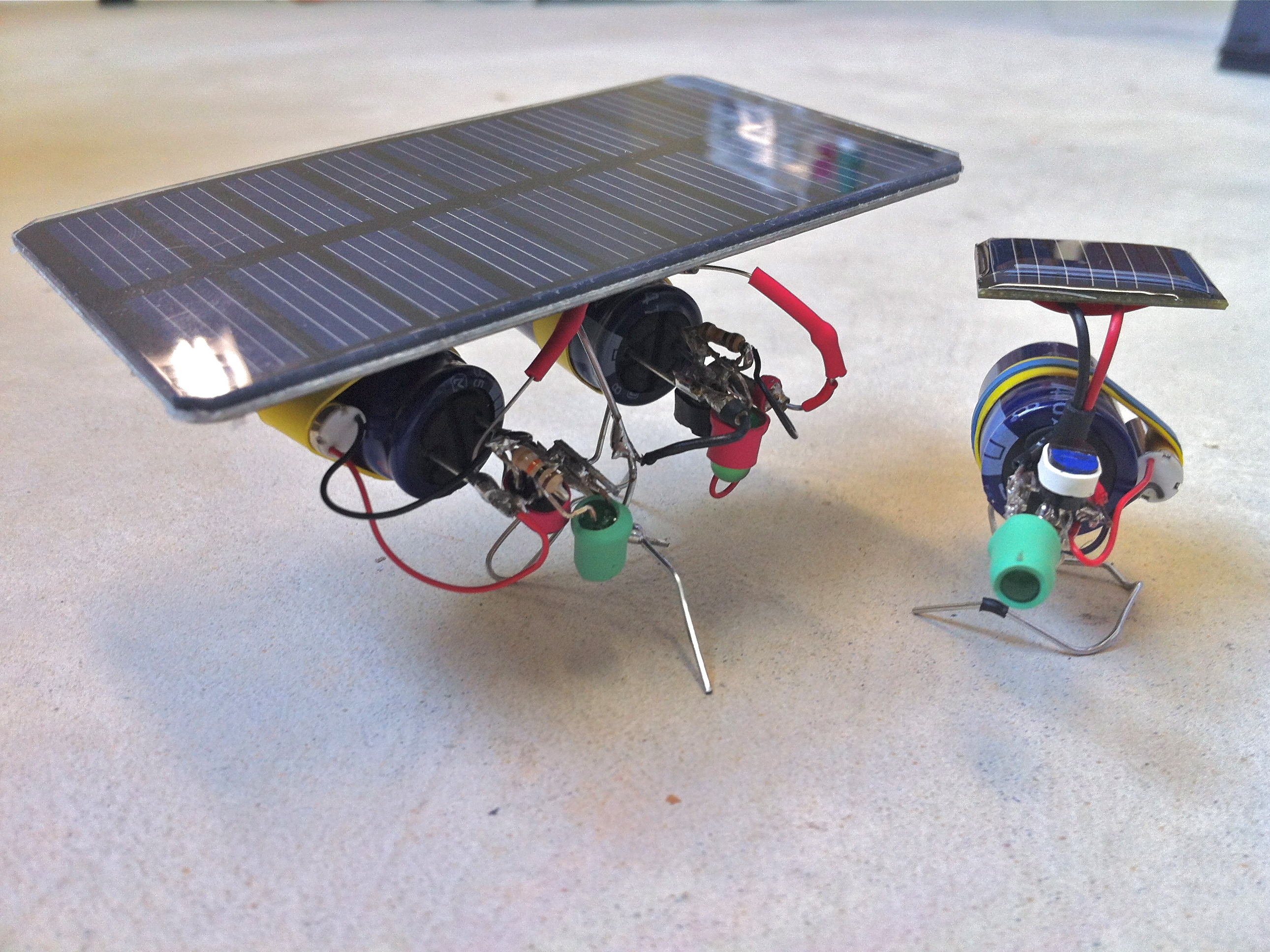
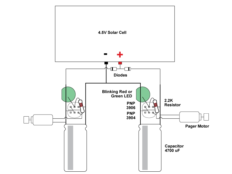
Making a Dual Engine Vibrobot
Insert wisdom here.
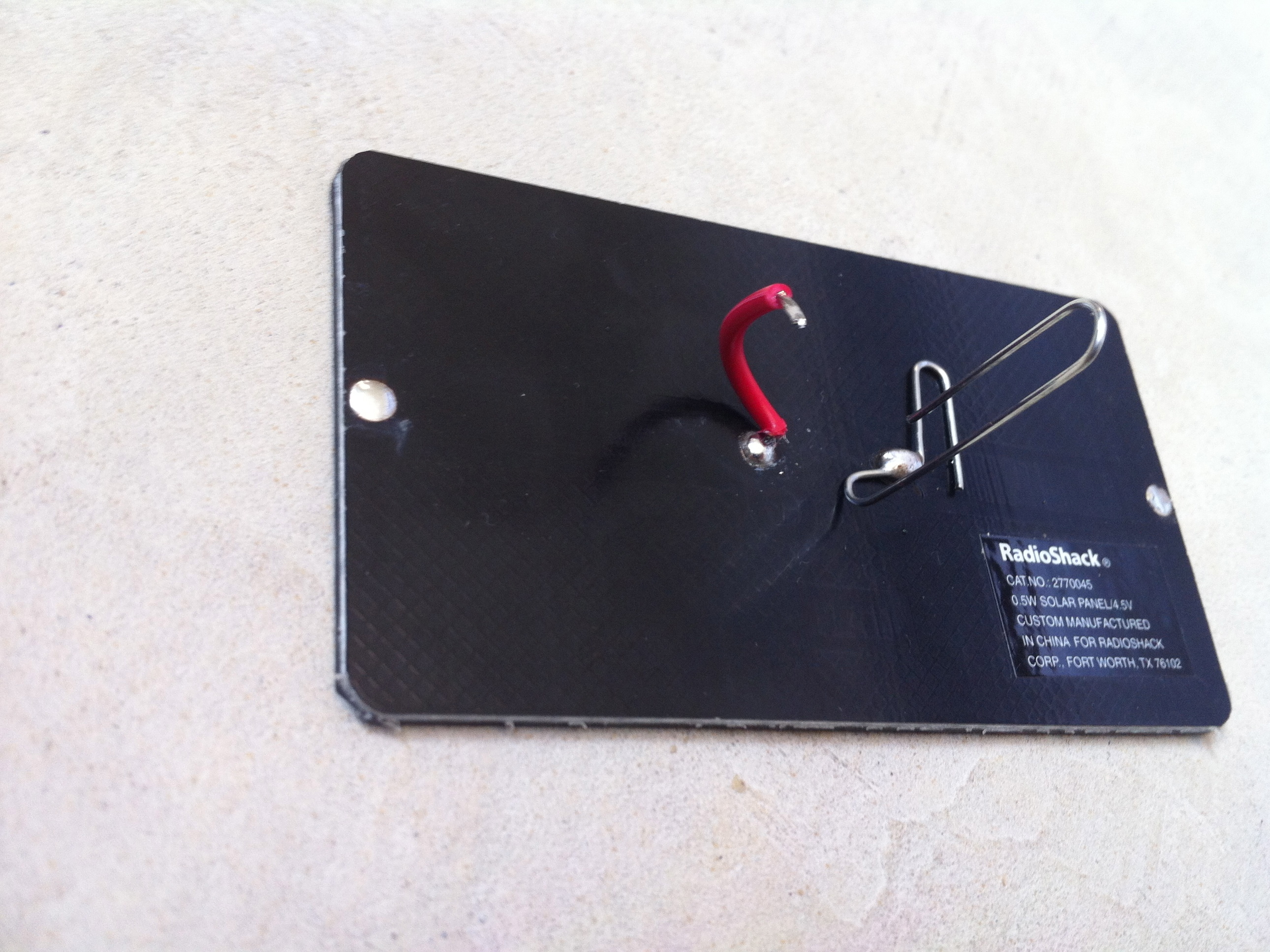
Preparing a Solar Cell
Solder a paperclip to the negative lead to both hold and serve power to the robot.
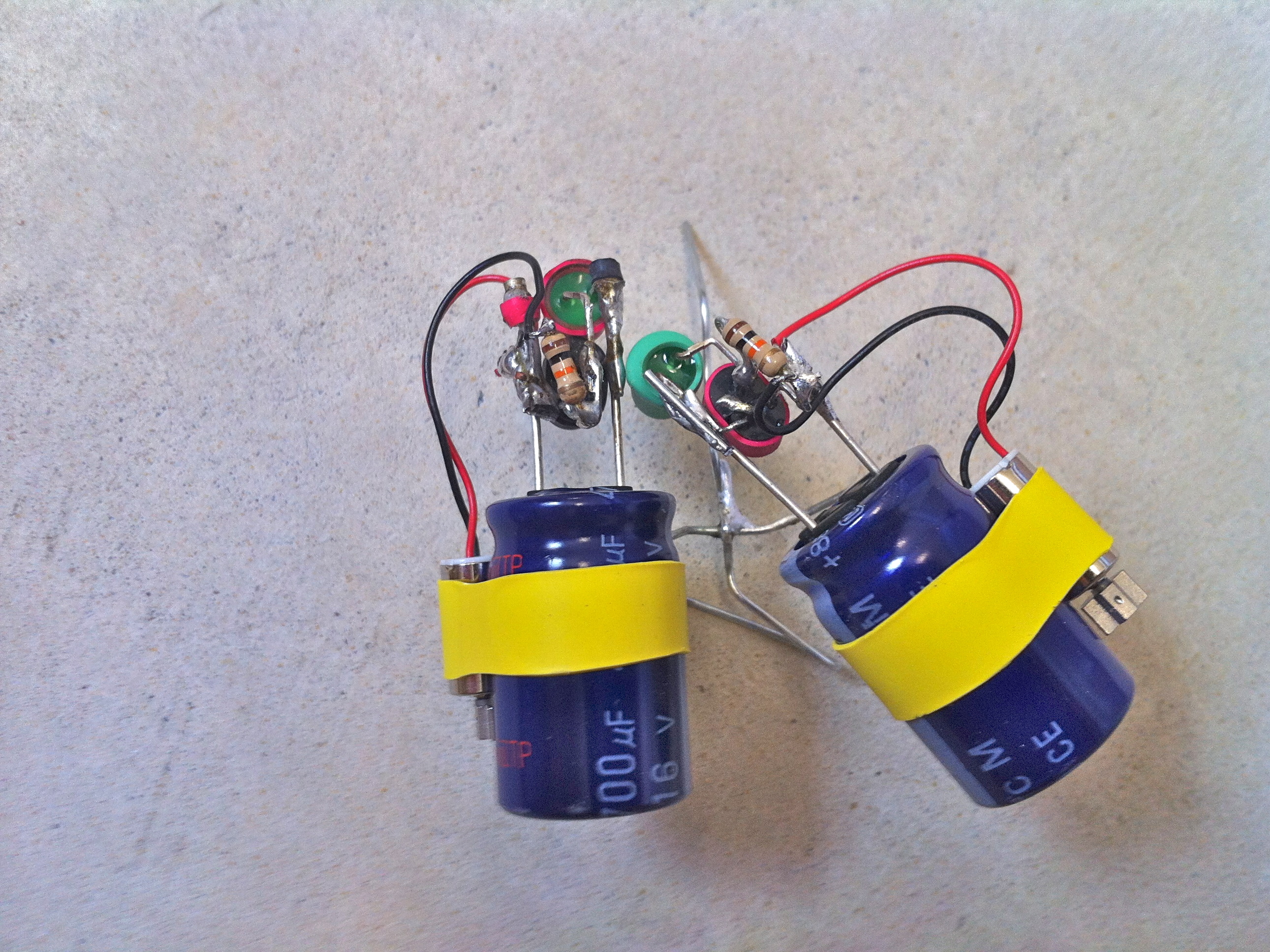
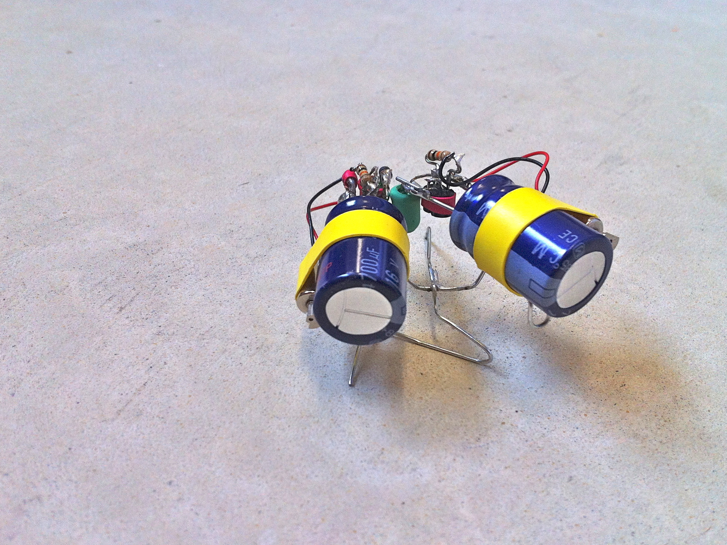
Assemble Dual Engine Vibrobot Chassis
Solder the paperclip base and chassis together.
Conclusion
The parts list is what is required per vibrating solar engine.