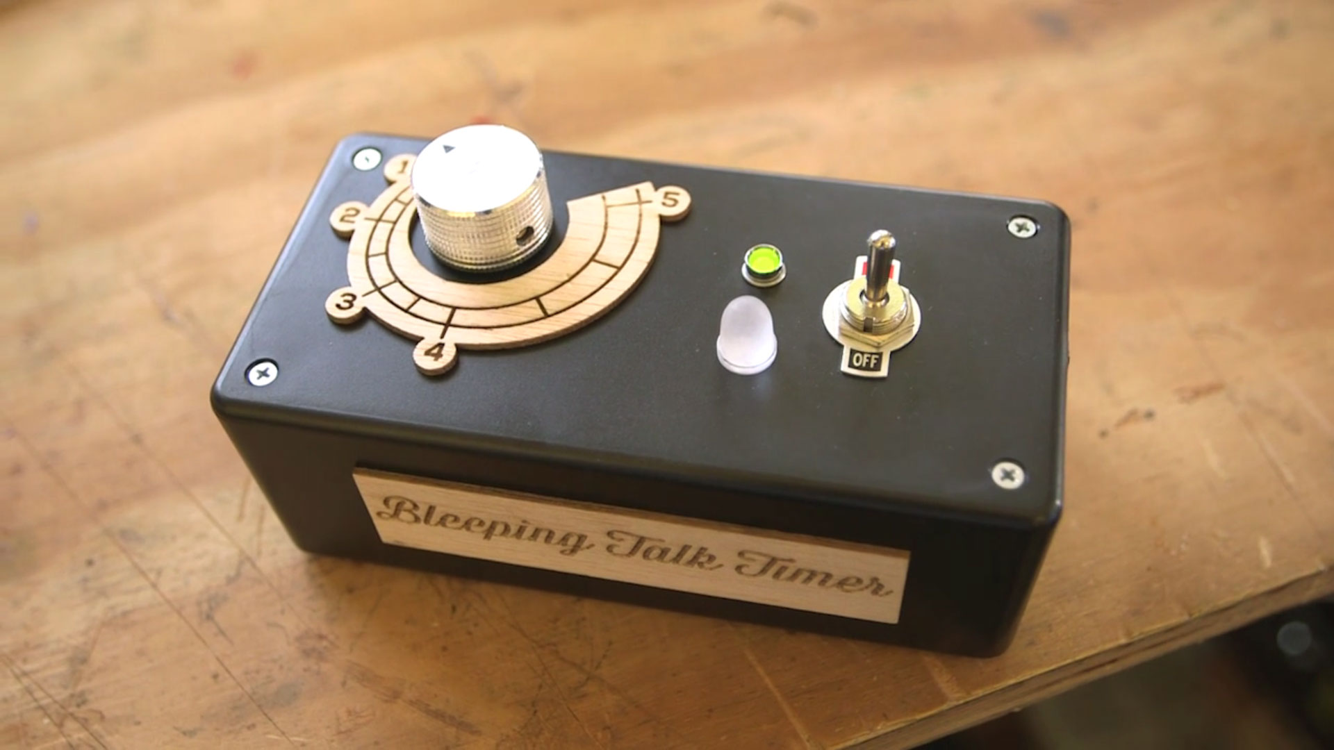
Do your co-workers talk too long at meetings? Do you use a ‘talking stick’ but there’s always that one person that never gives it up? Do you wish you could drown out pols during debates when their allotted time is up?
Bleeping Talk Timer is a simple countdown timer built using analog logic that triggers a piezo alarm when the time is up. No Arduinos here! No digital logic is involved. Just a simple circuit built with common components that keeps track of time. The circuit is built around the venerable 555 timer IC, a little chip that continues to fascinate me with its design, engineering, and applications, from LDR theremins to motor control to countdown timers. It’s estimated that a billion 555s are manufactured every year.
Ubiquitous as it is, note that this project does not use the low-power CMOS 555 “TLC” variant. The LM555 variant from RadioShack is capable of 18V of maximum input voltage, and we’ll be plugging a 9V battery into this circuit. Low-power 555s are better suited for applications where prolonged battery life or finer precision are required.
You can read up on the theory, background, and fundamentals of the 555 timer in Charles Platt’s Make: Electronics book, pp. 150–161, available from the Maker Shed and from RadioShack stores. Electronics Club also has a great run-down on the operations and applications of 555 timers.

Thus, to best explore and understand the operation of this circuit I highly recommend you breadboard it first. Because this is a countdown timer circuit that actual timing will vary based on components used. The minimum and maximum settings of the timer are partially controlled by the linear-taper potentiometer. Because we’re not using pin 1 of the pot, there is no “0” time coordinate. The connections from pin 2, the wiper, and pin 3, with this configuration, effectively made my timer range from ~35 seconds to 5 minutes. In my experiments I found there was a +/- margin of error of 3% (due to power dissipation from the electrolytic cap); this could add or subtract as much as 9 seconds to the timing when the pot is turned entirely to pin 3. Although truth be told the timer was more ‘precise’ the longer the time set, and it consistently hit 5:00 exactly.
So you’ll want to play with your components, take notes, and build accordingly. Here’s a snapshot of my breadboard layout:

I’ve color-coded the jumper connections, which I’ll go over in the project steps.
When the circuit is switched ON, the green LED will light up. When the countdown is complete, the green LED will switch off, the red LED will switch on, and the piezo buzzer will alarm! These two components will stay powered on until the circuit is switched OFF (or the battery dies). The piezo buzzer is loud, really loud. Annoyingly loud! 78dB loud :)
The video below shows the circuit in operation built into a project enclosure. Note this video is not real-time! I’ve purposefully clipped the video to show the LED-switching function (and I’ve considerately turned the audio off!):
OK let’s get building!
NOTE: I’m indebted to John Hewes at Electronics Club (formerly kpsec.freeuk.com) for use of this circuit, slightly modified for my components and design tweaks. His website has long been a valuable place to stop by to wrap my head around electronics theory and fundamentals. Thank you John!


