When you hear the word “wirebot,” you likely think of those cameras racing along wires above sporting events, unobtrusively capturing amazing action footage. Our wirebot will be quite a bit simpler, and a lot cheaper, however it offers quite a few cool possibilities.

Some of these applications include things like specialized holiday light displays or perhaps a wicked witch flying around the front yard on Halloween. My son wants to make a Star Wars TIE fighter flight path on the ceiling of his room using this type of wirebot.

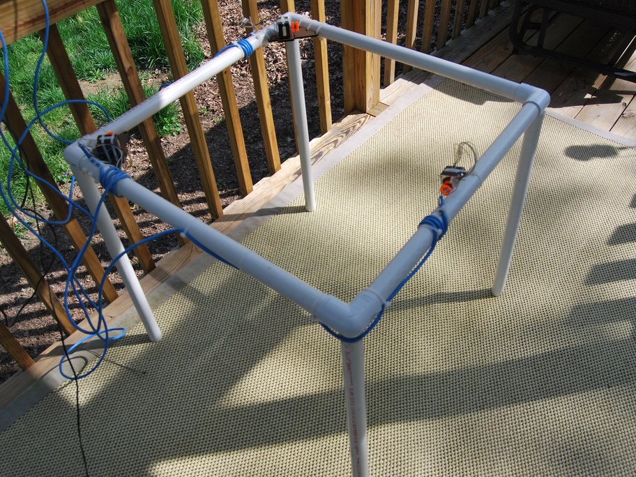
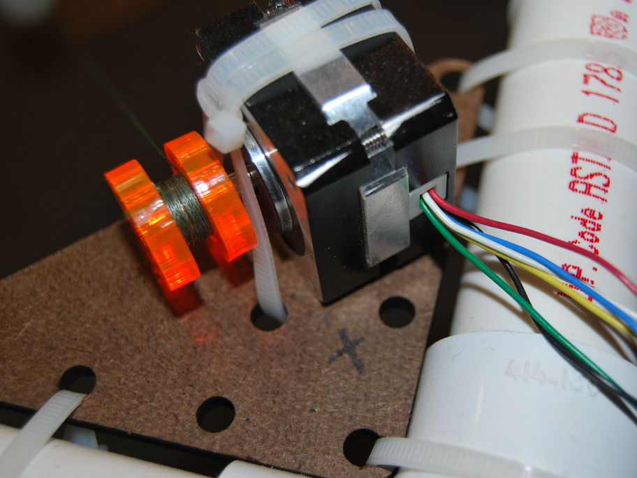
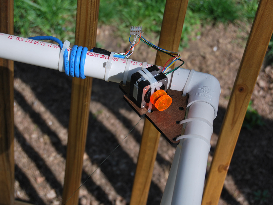
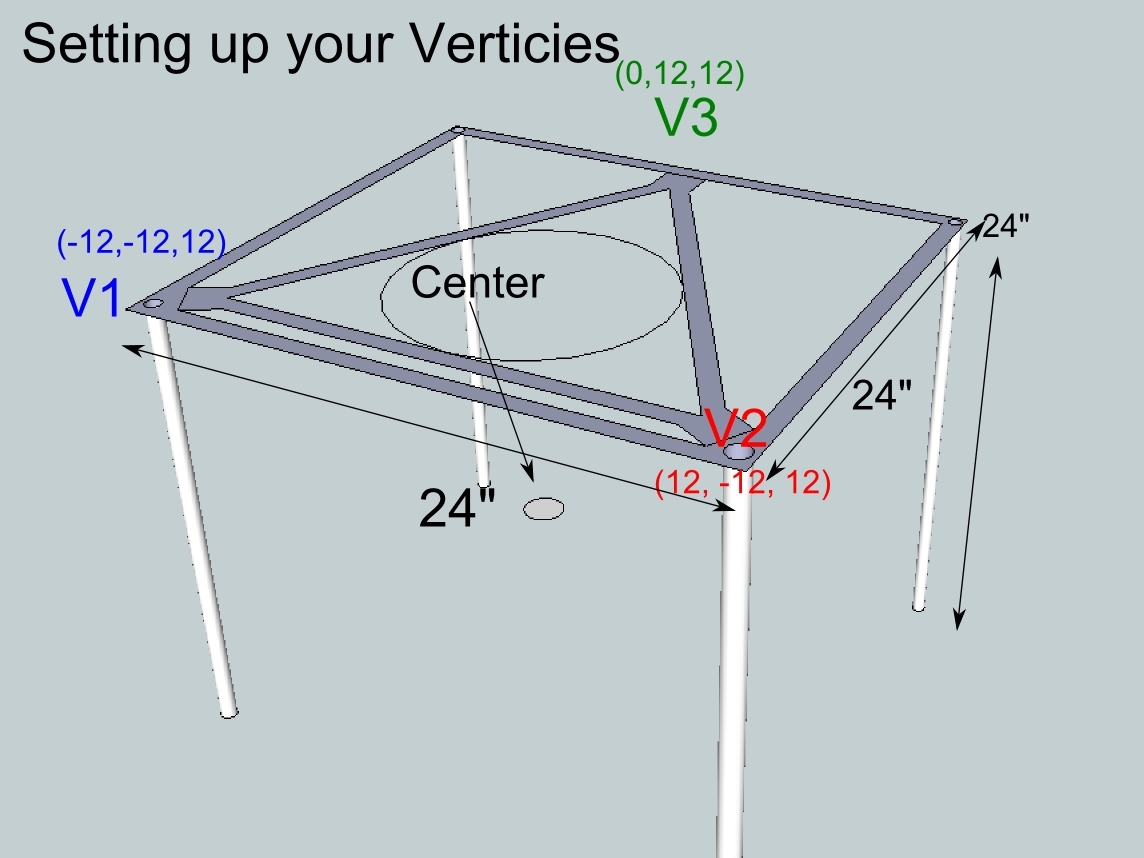
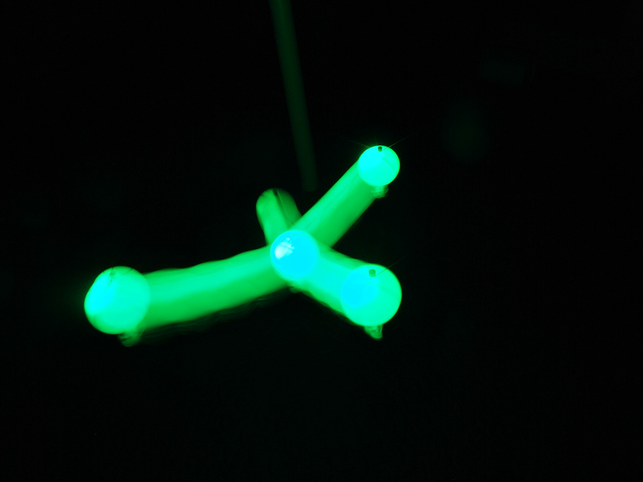
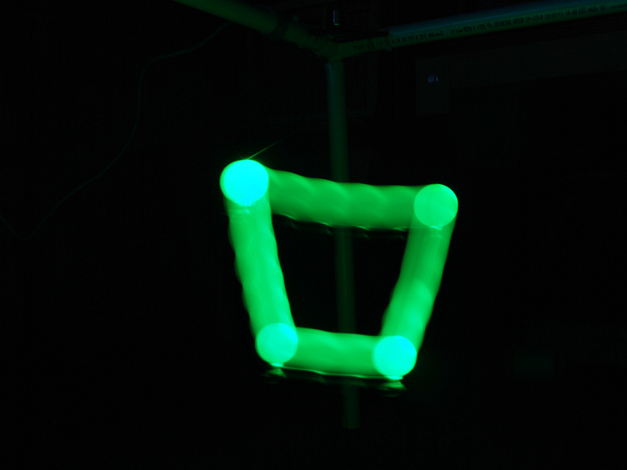
For my version here, I used a 24″ x 24″ x 24″ 3D cube made of PVC pipe as the frame for my rig. This limits the “working area” to about 8″ x 8″ x 8.” This size is good for demonstration purposes only. You’ll likely want to build a rig that affords a much larger working area.

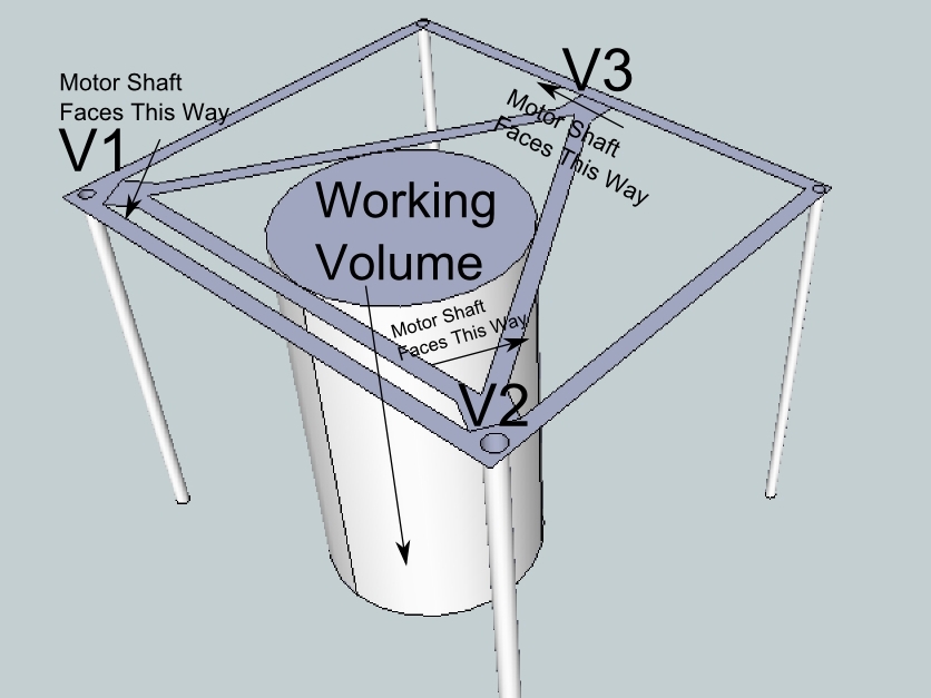
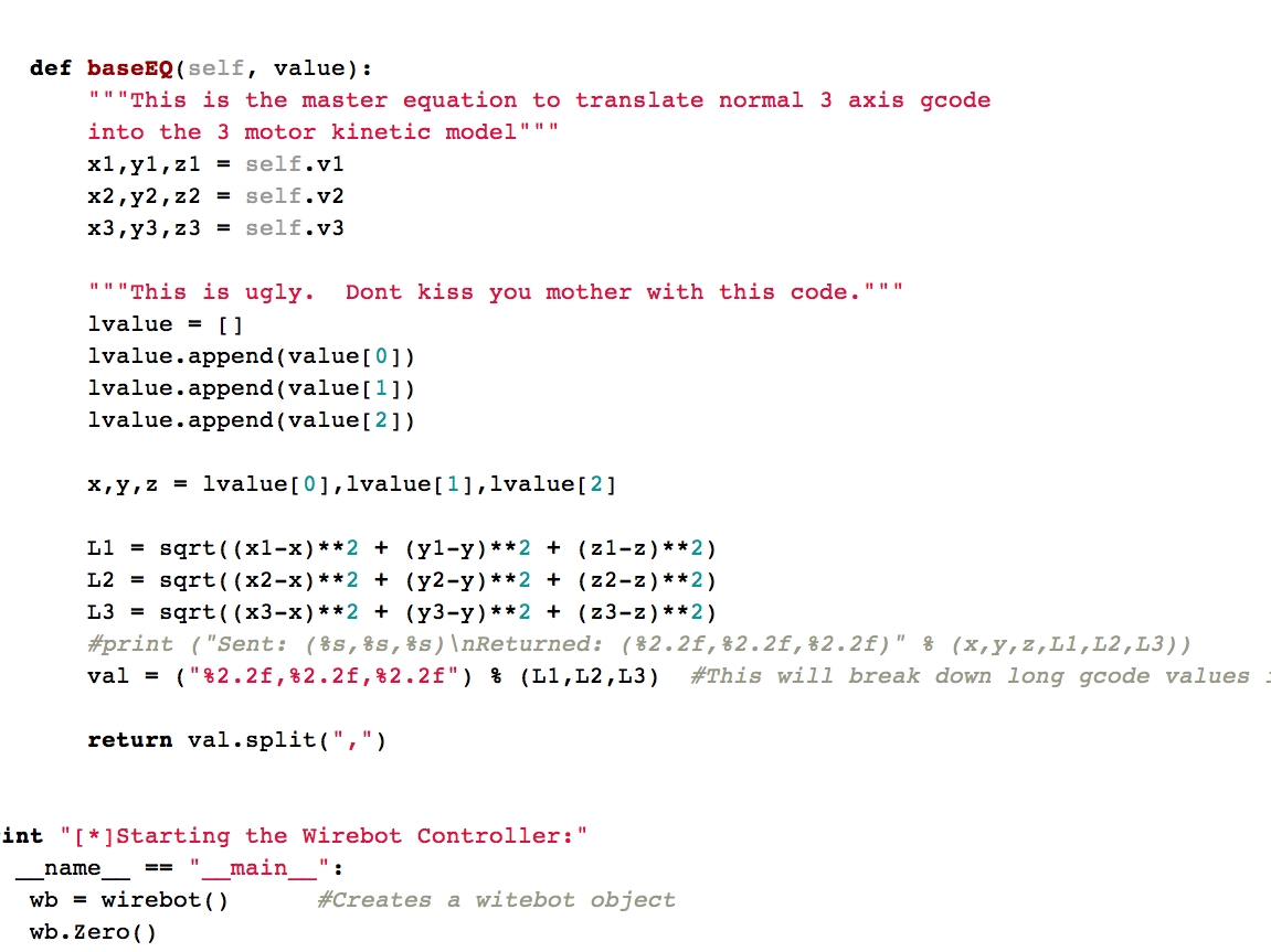
This concept behind this wirebot can be difficult to grasp. A more comprehensive explanation can be found in this blog post on my website. Special thanks to Alden Hart, my partner in crime on this project. Without him, figuring out the math for this it would not have been possible.

This guide assumes that you already have your stepper motors wired correctly and hooked up to the grblShield and that you are familiar with the grbl CNC framework. Should you need more information about grbl, or the grblShield, you can find everything you need here.

>> This project is brought to you by element14. Element14 is an information portal and online community for electrical engineers.

Project Steps

You will need to find your three spots for each point of the “triangle”. Choose a good space to work in (like an open porch), and mount the motors at each point of the triangle, or “vertices.” In my setup, I used a very small working volume. I have used a 24″ x 24″ x 24″ PVC cube. My setup is more or less an equilateral triangle. This is to illustrate a clear example. You can, however, use any type of triangle. For example, you could use part of your house and two trees in your yard. Or perhaps stakes in the ground, etc.

The drawing shows the establishment of the triangles and motor attachment points and the resulting “working volume.”

The third image shows the finished rig with motors attached (detailed in Step 2).

Now you need to attach the stepper motors to the 3 vertices you selected (the three points of the triangle). First, make sure your motors are all wired up before trying to attach them. I used CAT-5 cable to wire mine to the grblShield.

Make sure that the motor shafts face the same direction, meaning all facing clockwise or counter-clockwise. (See drawing in step 1.)

You need to wrap your line around your motor shafts now. For best results, the string should come off the spool pointing roughly towards the center, but any reasonable angle will do. I wound the strings so they feed off the top of the spools. I laser-cut some “spools;” however, you can use a 1/2″ wooden dowel from a hardware store cut and drilled instead. The size of your working volume will dictate the size of your spools. If you have a very large working volume (think: your front yard), you are going to want to create spools that are much larger in diameter.

I used some hardboard with some laser-cut holes. However, a drill and some right-angle cuts will work just fine.

For “mounting,” I chose to ziptie the motors, but you might want to use a permanent mounting for your setup.

Now we need to set up the verticies. This is not as complicated at is sounds. Look at the picture to get a clearer understanding. We need to set up all 3 vertices: V1, V2 and V3. You will need a measuring tape for this step.

This is easier if you have your lines tied together and attached to something. I used a ping-pong ball. Tie all three lines together in a simple knot. Then use a knife point to create a very small hole in the ball. In this hole, you will insert a screw to keep the line attached to the ball. Make sure the hole is a bit smaller than the screw. I used a 4-40 screw. Once the hole is done, insert the knot into the ball then screw the screw into the ball, trapping the line inside.

The wirebot coordinate system has an X, Y, Z origin (0,0,0) in the middle of the volume. Positive X moves to the right, positive Y moves towards the back, and positive Z moves up. To set up the vertices, determine the position of each vertex relative to the origin. Measure the vertex offset in X (left/right), Y (backwards/forwards) and Z (up/down) dimensions from an origin point in the center of the volume. Measure from the origin to the center of each spool.

In our drawing, you will see that from V1 to the origin (0,0,0) is 12″ on the X axis (Left to Right). 12″ on the Y axis (front to back) and 12″ on the Z” axis (down). Do the same measurements for your vertices and record them. We’ll put these into the Python driving program. One last thing to note: The V3 vertex will have a 0 in the X axis, as it is aligned with the origin (0,0,0) already.

The above example assumes the vertices are all at the same height, but they don’t have to be. Just enter the actual height from the origin. The example also assumes that the rear vertex is halfway between the left and right in X (centered), but it doesn’t have to be.

You can download the Python driving program here.

Once its downloaded, you’ll need to edit the source code to adjust the vertices to your recorded vertices from Step 3. I have detailed the settings that need to be changed in the Python code.

To run the program you’ll need the Python interpreter.

To run the wirebot program, you run Python wirebot.py.

If everything was configured properly in the wirebot.py script, then your bot should start moving straight up and down. This is a config mode. It helps to ensure that your motors are facing the right direction and your grblShield/motor connections are working properly.

Here are some images I drew using my wirebot. I inserted an LED throwie into the ping pong ball and then used an overexposure on my camera in the dark to illustrate the exact path my ball was taking.

Here is a video of the wirebot in operation.

Conclusion

For Arduino news, features, tutorials, a buyer's guide, and more, visit the Make: Arduino page.