Title
Did you know that, although they’re great for emitting light, LEDs are also capable of absorbing light? This idea is leveraged in the fantastic Maker Press book, Atmospheric Monitoring with Arduino, which goes into depth on using a variety of LEDs to detect light in the atmosphere. With a few simple components, you can build a device that’s capable of detecting sunrises, sunsets, and even haze and water vapor levels in the atmosphere.

All parts needed for this build are included in the LED Atmospheric Analyzer Kit, except an Arduino, USB Cable and jumper wires.

This project is pulled directly from the Atmospheric Monitoring with Arduino book, and begins on Page 51.

Project Steps

Make sure you have all the parts needed to build the photometer. Everything’s included in the LED Atmospheric Analyzer Kit except an Arduino and jumper wires.

If you haven’t soldered together your Maker Shield yet, hop on over to the Make Project and make it happen! Once your Maker Shield is ready to go, pop it on top of your Arduino and stick the mini breadboard onto the empty space of the board.

If you got a Sparkfun LCD with your order, have no fear! I’ll call out specific instructions for you.

If you haven’t done so already, flip to Page 37 of the Atmospheric Monitoring with Arduino book and start measuring the sensitivity of your LEDs. This process will help you get accurate readings from your photometer.

Once you’ve done that, start the photometer build by connecting a jumper wire from the Maker Shield’s 5V and GND headers to the mini solderless breadboard. Use another jumper to set up a GND rail on the opposite side of the board as well.

The speaker will give you audio feedback when certain events occur, like a new maximum reading from one of the LEDs. Solder a black wire to one of the speaker’s metal tabs and plug it into the rightmost GND rail of the breadboard. Solder a red wire to the other tab and plug that into D7 on the Maker Shield.

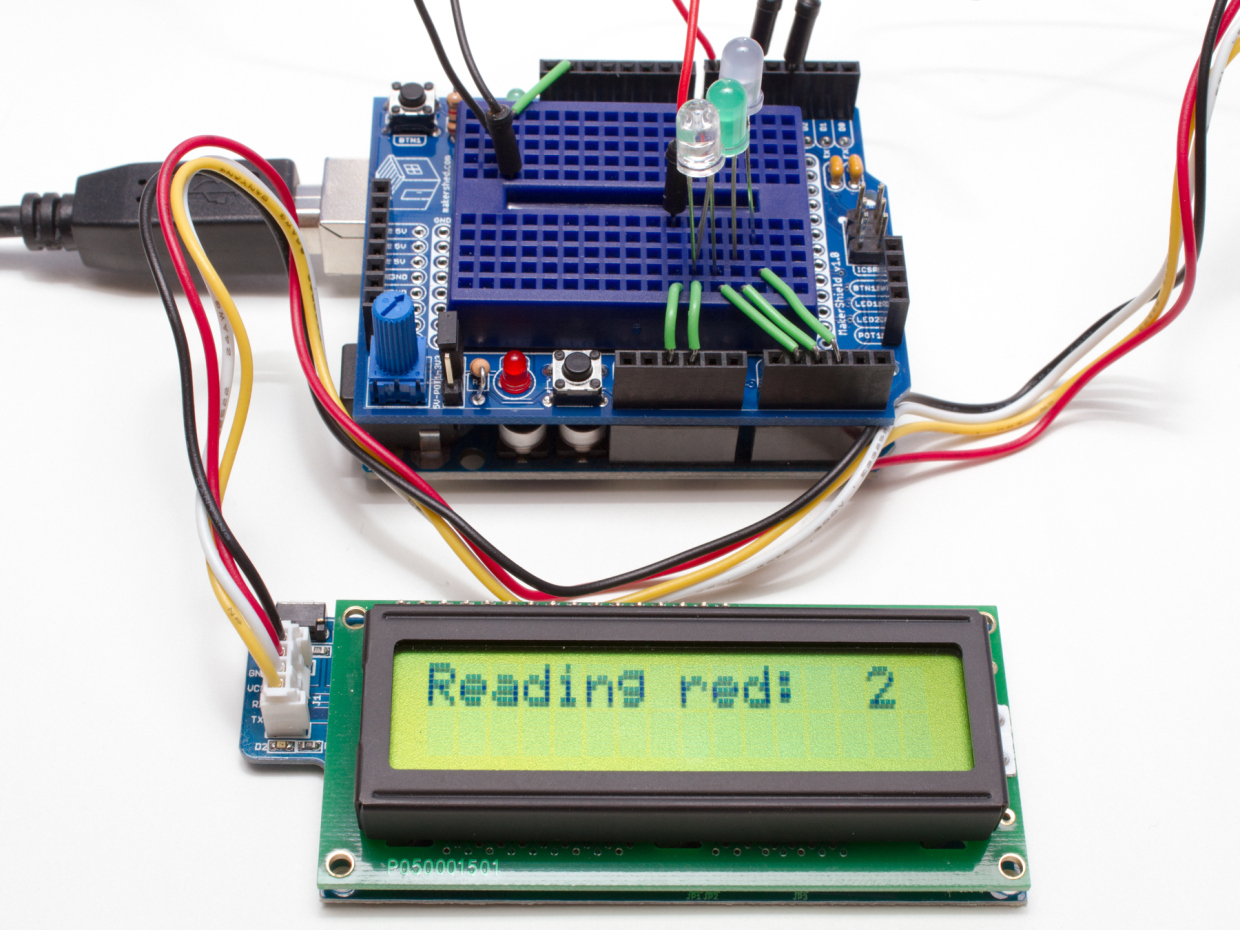
Now it’s time to plug in the LCD. Connect the four-pin cable to the LCD breakout board, and four jumpers to the other (black) end of the cable.

Hook the VCC pin (red) up to the 5V rail on the breadboard, the GND pin (black) up to the rightmost GND rail, the white (RX) to D5 on the Maker Shield, and the yellow (TX) to D3 on the Maker Shield.

If you have the Sparkfun LCD, connect the GND and 5V ports to the Maker Shield in the same way (except there’s no cable included, so just screw your jumper wires into the terminal blocks on the back of the LCD). Connect the RX port of the LCD to D1 (TX) on the Maker Shield.

Now we can prepare to install the LEDs. All three (Red, Green, and Blue) will use the same GND rail on the mini breadboard, but need their own Analog Pins. So, use three jumper wires to connect three rows of the breadboard to Analog pins 1, 2, and 3 of the Maker Shield.

Now plug in each of the LEDs’ short legs into the GND rail. The longer leg of the Red LED goes to Analog Pin 1, the long leg of the Green LED goes to Pin 2, and the long leg of the Blue LED goes to Pin 3.

And that’s it, you’re done! You can find some “Getting Started” code for the photometer here.