2014-03-11_13_37_52

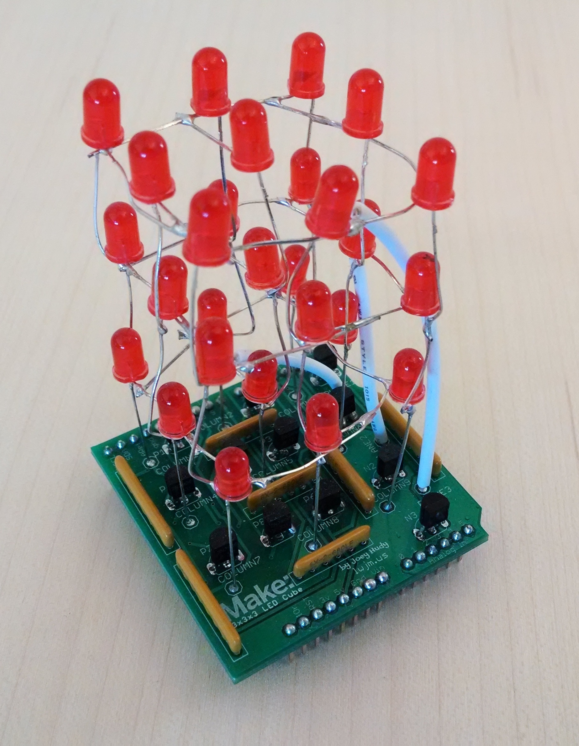
Welcome to the assembly instructions for the Maker Shed 3x3x3 LED Cube Arduino Shield Kit, originally created by Joey Hudy. With a bit of soldering, this fun kit shouldn’t take you more than an hour or two to complete. Read on for the full instructions.

Check out this video of Shed customer Tim Keeley’s 3x3x3 Cube in action! His code is available here.

YouTube player

These are the parts you should’ve received with your kit:
2014-03-11_13_57_39

What will the next generation of Make: look like? We’re inviting you to shape the future by investing in Make:. By becoming an investor, you help decide what’s next. The future of Make: is in your hands. Learn More.

Project Steps

2N3904 Transistors

To start, solder the 2N3904s in the bottom right spots (labeled N1 – N3). Make sure the flat side of the transistors matches the flat side of the drawing on the PCB.

2N3906 Transistors

Next, solder the other nine of the remaining transistors into place. These are labeled P1-P9.

Resistors

Next are the resistors – solder them where they belong (polarity doesn’t matter here).

Headers

Next, add in the male headers. The easiest way to do this is to insert the male headers into your Arduino, and set the shield on top. Then, just solder the headers!

LED Grid Subassembly, part 1

Now comes the trickiest part of the build: soldering the LEDs together. Basically, you need to bend all the negative (shorter) legs of the LEDs into a square and solder them together, to form three sets of nine.

Use the included lasercut guide to make sure the LEDs stay in the right position as you solder them together.

Once you have three grids of nine LEDs each, trim off the excess leads.

LED Grid Subassembly, part 2

Now it’s time to solder the three squares (of nine LEDs each) to each other. I like using a pair of helping hands to hold each row above the previous while soldering the positive, straight legs of the LEDs to each other.

The bottom square of LEDs’ positive legs should be soldered into the holes in the PCB, as noted in the second photo of this step.

The three stripped wires that connect each row go to their respective holes on the PCB – “Plane 1” for the bottom, 2 for the middle, and 3 for the top. It doesn’t matter what part of the square you solder the wire to – just make sure it’s connected to the horizontal, or negative, legs of the LEDs.

And that’s it! Plug it into your Arduino and download some code here.