Breadboarded alarm circuit using the Pico. Photo by Charles Platt
Get the Print or Digital version

This project is adapted from the staggeringly popular Make: Electronics Third Edition, which has been completely re-re-written with most photos and schematics replaced and updated!

During 2021 I started writing a third edition of my book Make: Electronics. One of the pleasures of this task was that I could rethink all the circuits, and with the benefit of hindsight, I saw how to simplify one project in particular: The intrusion alarm.

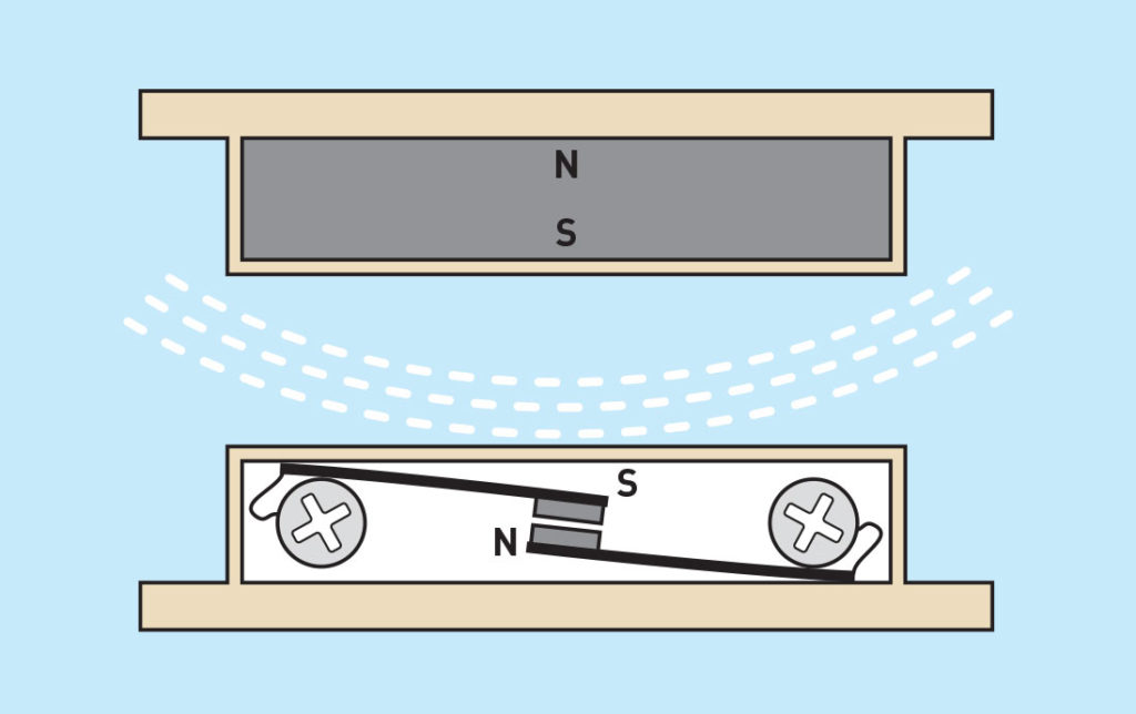
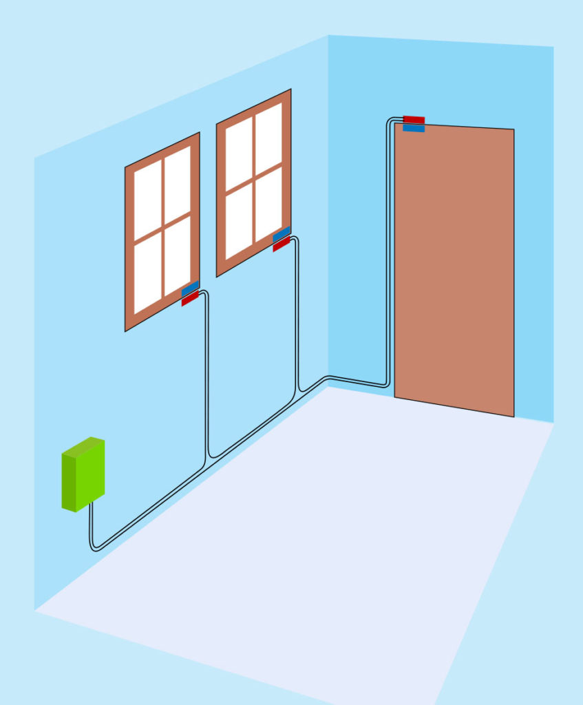
You’d think an alarm should be easy enough. Just place some sensors on doors and windows, wire them to a beeper, and — job done!

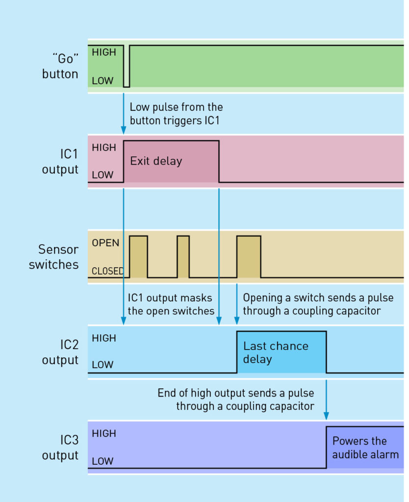
But it’s not so simple. First, the alarm has to notify you that all the doors and windows are closed before you activate it. Then you need a delay (which I call the Exit Delay) so that you can leave the area without causing the alarm to start making a noise. When you come back, you need another delay (which I call the Last Chance Delay) to prevent the alarm from beeping or wailing till you have a last chance to switch it off. The diagram below shows what I mean.

Overview of alarm behavior. Photo by Charles Platt

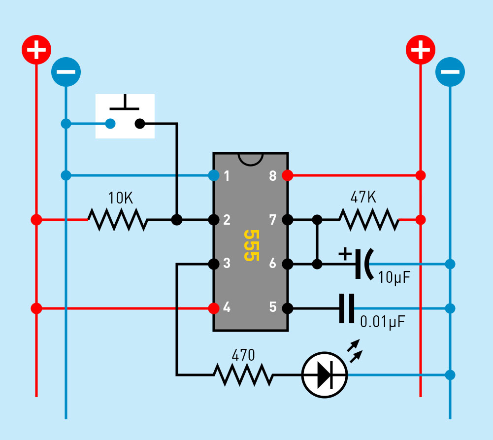
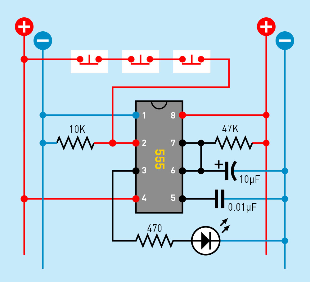
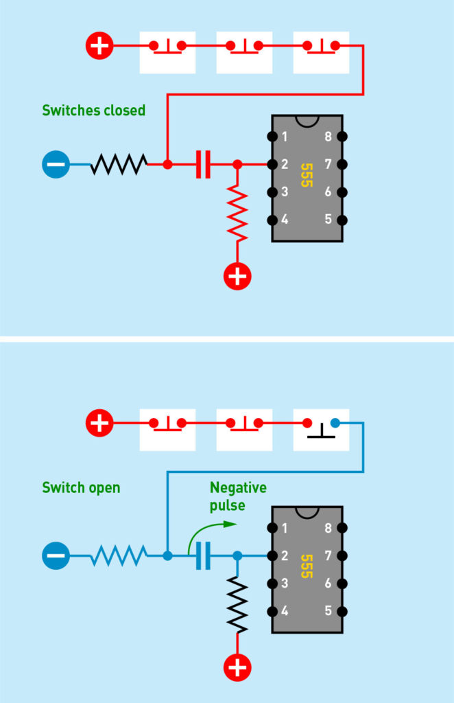
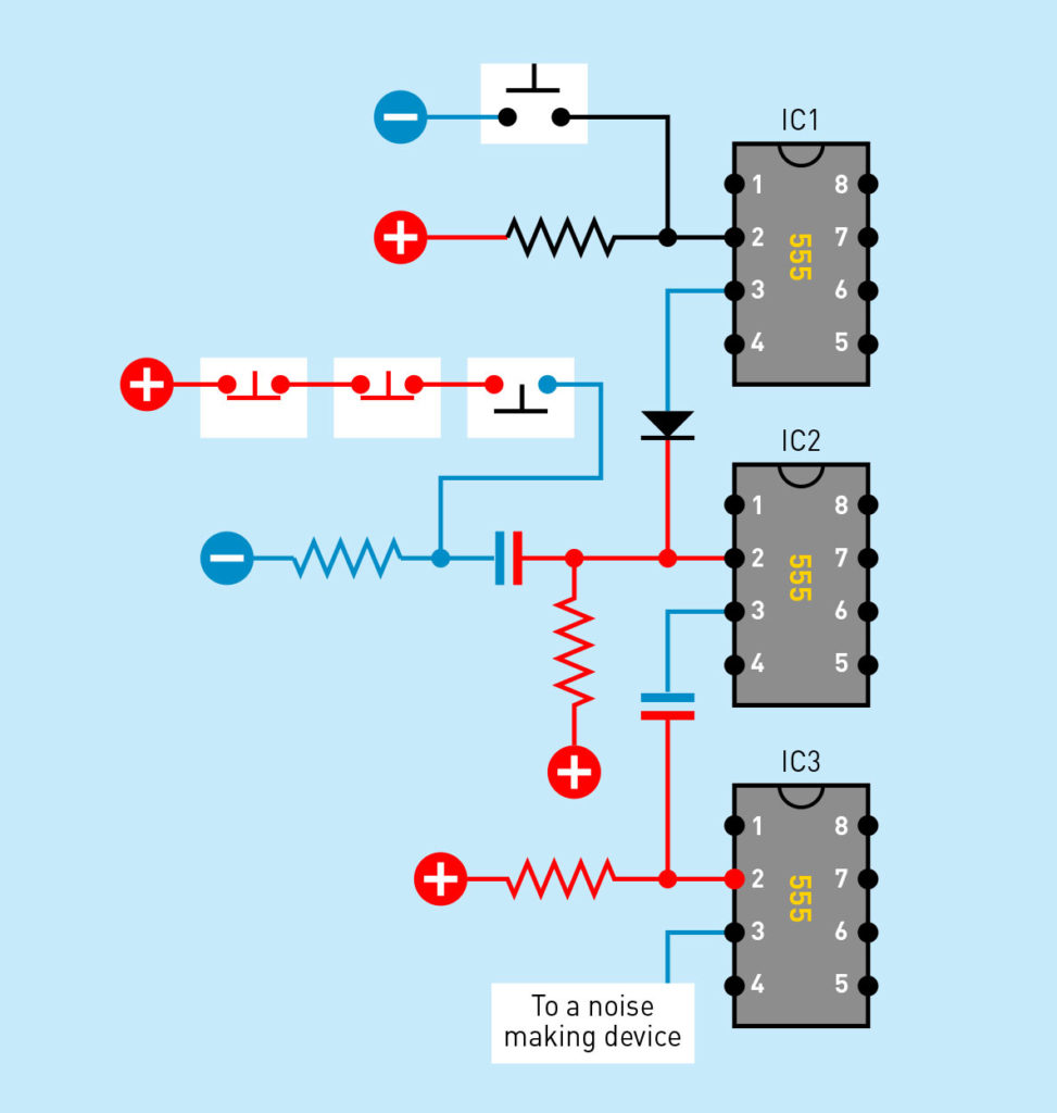
The word delay suggests a component that measures time. That could be a timer, couldn’t it? In fact you can build this circuit entirely with three 555 timers — the old-school chips that have outsold all other chips ever made. Along the way you’ll learn about pullup and pulldown resistors, diodes, and coupling capacitors, which can be useful in many other applications.

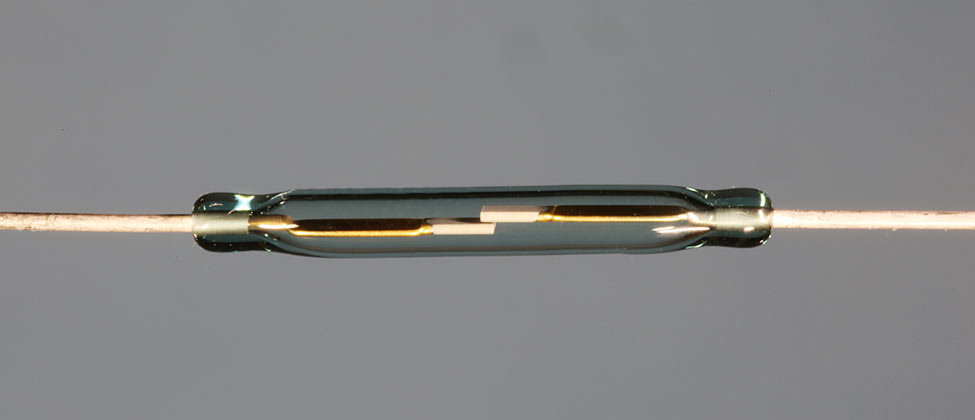
IC1, IC2, and IC3 are acronyms for integrated circuits, which are the three 555 timers.

Using a Pico

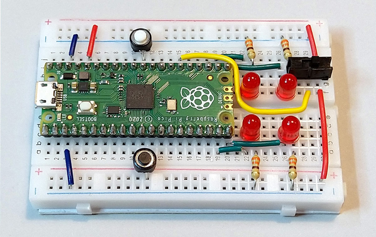
You can, of course, use a microcontroller instead of 555 timers. My collaborator Fredrik Jansson likes the new Raspberry Pi Pico chip, because it’s so powerful and so affordable, so he wrote some code for it in MicroPython to behave the same way as my circuit, as shown in Figure . His comments in the code show you what the alarm program is doing at each step; you can type it in as you see it here, or download it.

# Raspberry Pico version of Make: Electronics alarm
from machine import Pin
from time import sleep
# LED outputs
l1 = Pin(17, Pin.OUT) # Switches are closed GP17
l2 = Pin(16, Pin.OUT) # Time to leave GP16
l3 = Pin(14, Pin.OUT) # Alarm is triggered GP14
l4 = Pin(15, Pin.OUT) # Alarm! GP15
# Inputs with pulldown
go = Pin(8, Pin.IN, Pin.PULL_DOWN) # Go button
sensors = Pin(20, Pin.IN, Pin.PULL_DOWN) # Sensor switches
# show sensor state on LED 1
l1.value(sensors.value())
# function to be called when the sensor pin changes
# show sensor state on LED 1
def sensors_change(p):
 l1.value(sensors.value())
# connect function to the sensor pin change interrupt
sensors.irq(trigger=Pin.IRQ_RISING | Pin.IRQ_FALLING,
 handler=sensors_change)
# The alarm logic starts here
# Wait for GO button press
while go.value() == 0:
 pass
l2.value(1) # time to leave
sleep(10) # exit delay
l2.value(0)
# wait for sensors to open
while sensors.value() == 1:
 pass
l3.value(1) # alarm is triggered
sleep(10) # last chance delay
l3.value(0)
l4.value(1) # Alarm!
# the alarm stays on until reset/power-off
while True:
 sleep(1)
Breadboarded alarm circuit using the Pico. Photo by Charles Platt

Fredrik’s breadboarded circuit for the Pico is shown above, using sensor switches that are normally closed, and adding a reset button to boot the Pico. The components look wonderfully simple, but of course you do have to write the program, upload it, test it, track down your syntax errors, and upload it again.

Personally I prefer old-school components, because I think they’re fun — and you will learn about concepts such as diodes, pullup resistors, and coupling capacitors as you go along.

Project Steps

Reed Switches

A basic alarm installation often uses pairs of sensor modules. One module contains a magnet, while the other contains a reed switch.

This type of switch consists of a sealed glass capsule containing two magnetized contacts (top). A magnetic field will push them together (if they are normally open) or pull them apart (if they are normally closed). Letters N and S stand for north and south, the two poles of a magnet (Bottom).

For an alarm circuit, you will need the type of sensor with contacts that are normally open. You mount each magnetic module on a door or a window, and you mount each switch module on the adjacent frame so that it almost touches the magnetic module when the door or the window is shut. In this way, the magnets hold the reed switches closed.

The magnetic modules are blue rectangles while the switch modules are red and the alarm is in a green box. Because the switches are wired in series, if any switch opens, the continuity of the circuit is interrupted. This is known as a break-to-make type of circuit, because any break in the circuit — at any window or door — makes the alarm go off. Another advantage is that the circuit will also be triggered if someone tries to interfere with it by cutting the wire.

Triggering a Timer

The diagram shows a breadboard-layout test circuit for a 555 timer in monostable mode. Pin 2 is the “Trigger Pin,” and when its voltage is pulled down below 1/3 of the supply voltage, this triggers the timer, which emits a high pulse from Pin 3, the Output Pin. The duration of the pulse is controlled by the 47K resistor and 10µF capacitor, which create a pulse of about 3 seconds. You can learn more about 555 timers from any introductory source about electronics (including my own book, naturally).

You must not allow Pin 2 to float at an indeterminate voltage, so a 10K pullup resistor keeps the pin near the voltage of the power supply until the pushbutton bypasses it with a direct connection to negative ground. Pullup and pulldown resistors are important features of countless circuits.

I wanted to use the timer in this mode as IC2, the Last Chance Delay timer, but I encountered a problem. When a door or window is opened in an alarm circuit, it doesn’t make a connection, like the pushbutton in the diagram above. It breaks a connection.

I had to revise the circuit (above), where I have indicated the sensor switches as three normally-closed buttons. Because they are attached to the positive power supply, Pin 2 is normally positive, as shown. But if any of the sensors are opened, the positive connection is cut off, and a 10K pulldown resistor makes Pin 2 negative, which triggers the timer.

Next I ran into another problem. What if someone should open a door or window, and leave it open indefinitely? The voltage on Pin 2 will stay low indefinitely, creating a Last Chance Delay that lasts indefinitely. If the delay doesn’t end, the alarm will never start to make noise. Not good!

My answer was to insert a coupling capacitor and a pullup resistor. So long as all the switches are closed, everything is stable. The voltage to Pin 2 remains positive, and the timer doesn’t do anything. But when a switch is opened, the pulldown resistor (on the left) takes over, causing a short negative pulse to pass through the capacitor.

This is the odd thing about capacitors. They block DC current, but if you change the voltage suddenly on one side, a short pulse of current seems to emerge on the other side. This is known as displacement current, and at the risk of promoting myself, I have to tell you that I explain this concept elsewhere in my book Make: Electronics. The concept is often misunderstood, so I have included a thorough explanation in the Third Edition.

This circuit will only work if the resistors and the capacitor are chosen correctly. How did I know what values to use? Well, I didn’t! I just tried various values while using an oscilloscope to check the voltage on Pin 2, until I found an arrangement which worked reliably. A pullup resistor of 47K, a pulldown resistor of 10K, and a capacitor of 0.47µF was a good combination.

Note: Oscilloscopes are much cheaper than they used to be. For around $100, you can buy either a handheld oscilloscope or a “virtual oscilloscope” which plugs into a USB port on a computer and generates a higher-res display. This is a very valuable tool if you want to build circuits.

Maybe my arrangement with two resistors and a coupling capacitor seems complicated, but it keeps the timer happy, and if you want a circuit to function reliably, the components must be happy at all times.

The Exit Delay

Having figured out how to trigger IC2, my next step was to think about IC1, which creates the Exit Delay. During this delay, IC1 has to prevent IC2 from being triggered when you open a door to leave the area.

The diagram above shows a simple way to do this. First, you press the “Go Button” when you’re ready to go, and this starts a single high pulse as the Exit Delay from IC1. (No need for a coupling capacitor with the Go Button, because you will only press it briefly. You won’t sit there holding it down.)

The high output from IC1 passes through a diode that connects directly with the Trigger Pin of IC2. While this is going on, if an opened door or window creates a negative pulse, it’s not powerful enough to get through, because the voltage through the diode overrides it.

How could I know this? By testing it. That was the only way.

I added a diode because the output from IC1 is normally low, when it isn’t being triggered, and I didn’t want the low output to get through to IC2.

The Sequence

The sequence may be hard to understand, so I’ll sum it up. You press the Go Button to start IC1, and it generates a high output that lasts long enough for you to leave the area. Now IC2 doesn’t notice if you open a door, because the voltage from IC1 prevents IC2 from being triggered.

At the end of the exit delay, IC1’s output goes low, but this is blocked by the diode, so it doesn’t have any effect on IC2. The pullup resistor now keeps Pin 2 high on IC2, but if any door or window is opened, the negative pulse breaks through and triggers IC2.

When IC2 is triggered, its output goes high for a limited time — long enough for you to switch off the alarm, if you’re the one entering the space. If you don’t switch off the alarm, the output from IC2 goes low at the end of its cycle, and this will start some noise — somehow. I haven’t described that part yet.

The diagram may help to clarify the sequence, in theory at least.

The Never-Ending Noise

When I saw that the output from IC2 would drop from high to low at the end of the Last Chance Delay, I realized I could couple it through (guess what) another coupling capacitor, to trigger IC3. This connection is shown in the diagram above, which shows the components at a moment when none of the timers is active.

Now, let’s suppose there is an intruder, and IC2 triggers IC3. How long should its output stay high? Well — indefinitely! You want the sound of the alarm to continue until an authorized person (such as you) turns it off.

Fortunately there is a way to wire IC3 so that when its output starts, it never stops. This is known as bistable mode. The timer will deliver a high output until you shut it down. The secret is to eliminate the timing capacitor which is normally attached to Pin 6, and wire Pin 6 to negative ground.

You can see this in the diagram above, which shows a complete schematic for the circuit. The only thing missing is some kind of noise maker, but that could just be a piezo beeper which has an audio circuit built in. The diagram below shows how the circuit can be breadboarded, using LEDs for testing purposes.

Here’s your testing procedure:

First close the switch at the top of the breadboard, which simulates closing all the doors and windows where the alarm system has been installed. The top LED lights up to confirm the continuity.

Now you can press the Go Button, triggering IC1, which lights the “Time to leave!” LED. While this is on, the Exit Delay is in effect. You can open the sensor switch and nothing will happen. The circuit allows an exit delay of only 3 seconds for testing purposes, but that’s sufficient for you to open and close the sensor switch (the door).

At the end of the Exit Delay, the second LED goes out. Now the alarm is armed and ready, and if you open the sensor switch, this allows a negative pulse to trigger IC2, which begins the Last Chance Delay. During this period, the third LED lights up to warn you that you have one last chance to switch the alarm off.

At the end of the Last Chance Delay, the output from IC2 drops to a low state, which sends a negative pulse through the coupling capacitor to trigger IC3, which switches on and keeps itself switched on, because it is wired in bistable mode. The last LED lights up to tell you that if you substitute a noise maker on the output of IC3, it will start making noise (and keep making noise until you turn it off).

To increase the delays from 3 seconds to 30 seconds, replace the two 47K resistors on the right with 470K resistors.

If you’re wondering about the purpose of the 10µF and 100µF capacitors on the left, they prevent the 555 timers from triggering themselves when you first apply power to the circuit.

Finishing Touches

Naturally if you want to create a finished version, you would solder the components to perforated board and put it in a project box. The top photo shows some components with a template for drilling holes in the lid of a box. I added an extra oscillator circuit to drive the speaker. The bottom photo shows it assembled.

One word about installing sensor modules on windows and doors: Remember, they have to be in series, not in parallel. The photo shows how to do this with two-conductor wire.

I skipped some details in describing the project here, because I don’t have unlimited space in the magazine. You’ll find more explanations in my book — together with a confession describing how the circuit didn’t work properly in the first version that I tried. I was happy when that happened, because when something doesn’t work, it’s always a valuable learning experience.