This project is part 2 in the building a robot arm tutorial. In the first part I show how to design the robot arm and in the third part I show how to design the mount section. Part four will show how to add control with an Arduino.
In part one of making a robot arm, we explored a lot of things like 3D computer aided drafting software, or CAD for short, and 3D printing. We also explored how to design things that will interface with real world objects, like our stepper motors. Still, we only built out one small part of the robot, the core section that gives the arm reach and good articulation. Obviously this small section of a robot alone can’t do many cool things so we need to add to it. Using the tools that were discussed in my previous post, the CAD software and its ability to create digital forms, we will generate more parts that interface with the motors and the section of the arm we already designed.
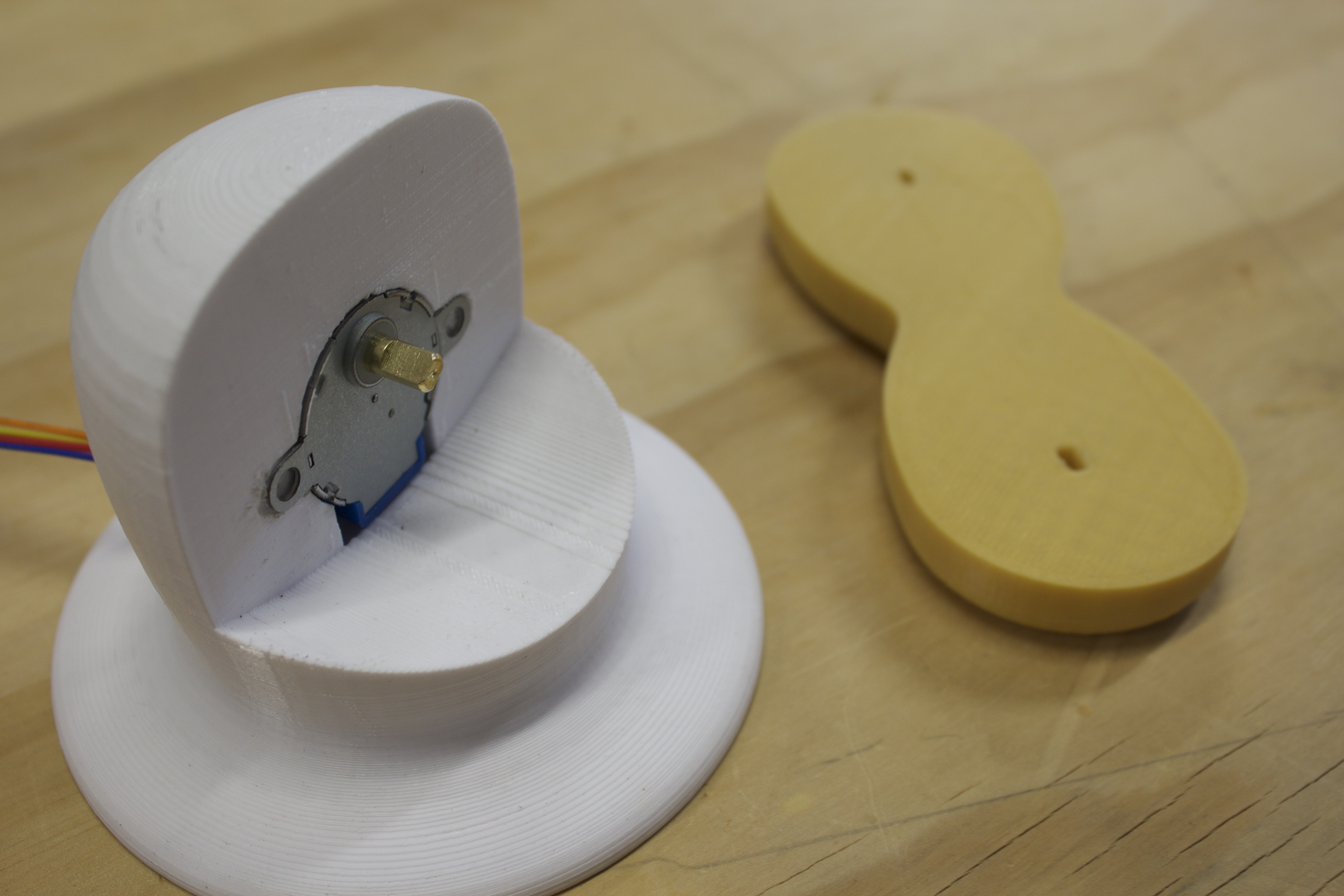
The first addition is the base. In this tutorial, we will go over how to create a base for the robot arm and how to shape the base structure so that it might accommodate one of our stepper motors. We will cover a number of new digital CAD tools including how to create perfectly round structures that fit our needs and how to integrate the motor into the base to support the robot arm.
We will again be using the Dremel Idea Builder because of its reliability and speed.
As we continue to design and build this arm, there is opportunity to add and modify the function and structure of the robot. Once we lay the groundwork for how to design all the critical pieces and get it moving, we will be able to change the design to fit particular use cases and functions. This includes being able to scale the arm to use bigger motors and move large objects. Still, we will need to to make sure all of our component parts work before we start experimenting.
One more thing to keep in mind, as we design make sure to save and make copies of all your files. If we do go back to edit and change our designs, then copies will allow us to make lots of different versions and iterate on our ideas.
Project Steps
Where the Robot Arm Left Off
When we finished with the robot arm, we had modeled our arm section along with the stepper motor we are using. It is very important to model all of the stepper motor at this stage using calipers as accurately as possible.
Orthographic View
This particular view is specific to Rhinoceros, the program I used, but not to worry, viewing objects in the front, side, and plan view is possible in any modeling software. If you are unsure how to do so, consult your help menu or you should be able to find information online. I am showing you this, though, because we will use it in a moment.
Draw a Circle
To start the base, start by drawing a circle.
Draw the Silhouette of the Base
Draw the line that will define the silhouette of the base. We do this by drawing a line from the center of the circle straight up; I made mine 3″ tall to fit the robot arm base in the printer.
Next, use a curve to draw the silhouette starting from the top of the line all the way down to the circle that we have at the base. We do this in plan view to make sure we have a perfectly orthogonal curve. This will be important in the next step.
Revolve the Curve
Revolve the orthogonal curve that we drew around the middle line. This will create our base’s general shape. Make sure that you rotate it all 360° and make sure the top of the base is wide enough to surround the motor. I will explain that more in later steps.
Close the Base so it is Solid
Add a closed circular plane to the bottom of the base and join it to our new shape. This will make it a solid object. If you are using Solidworks or Sketchup this shouldn’t be a problem.
Prepare Your Motor Model
Finally, get the motor ready by making a copy of it. Do this so that there is always a model of the motor that is correct.
After making a copy, scale the model up by about .1″. We do this because of the inaccuracy of 3D printing. While it might seem like a 3D printer is very accurate the reality is when it comes to manufacturing interconnecting components, most printers won’t print your piece perfectly.
Boolean Remove Half of the Top
Now, draw a cylinder with the center on the top of the robot arm base and the bottom reaching a little more than half way down. Make sure it is thick enough to completely eclipse on half of the top of the robot arm base.
After, use a boolean command to subtract the cylinder from the base. This will leave us with room for our arm segment to move around in.
Motor Placement and Final Subtraction
Finally, place the scaled up motor inside the remaining half of the base. Make sure the rotating part of the motor is centered along the line we used to revolve the original shape; that way the arm segment won’t look strange once it is placed on the base.
Finish by creating a box underneath the motor that protrudes out the back of the base, this will be for wire access. Again, use the boolean subtraction and remove both the motor and the box from the robot arm base. This leaves us with a printable object.
Print and assemble!
It is time to print the base using the Dremel Idea Builder and assemble it using the stepper motors.