This project is part 3 in the building a robot arm tutorial. In the first part I show how to design the arm and the second part shows how to design the base. Part four will show how to add control with an Arduino.


done1

So far in designing our robot arm we have designed and printed the base and the modular arm segment. Now, after designing the basis of our robot, we are ready to design and print the final piece. Still, this piece is special; this is how we mount something to the arm.

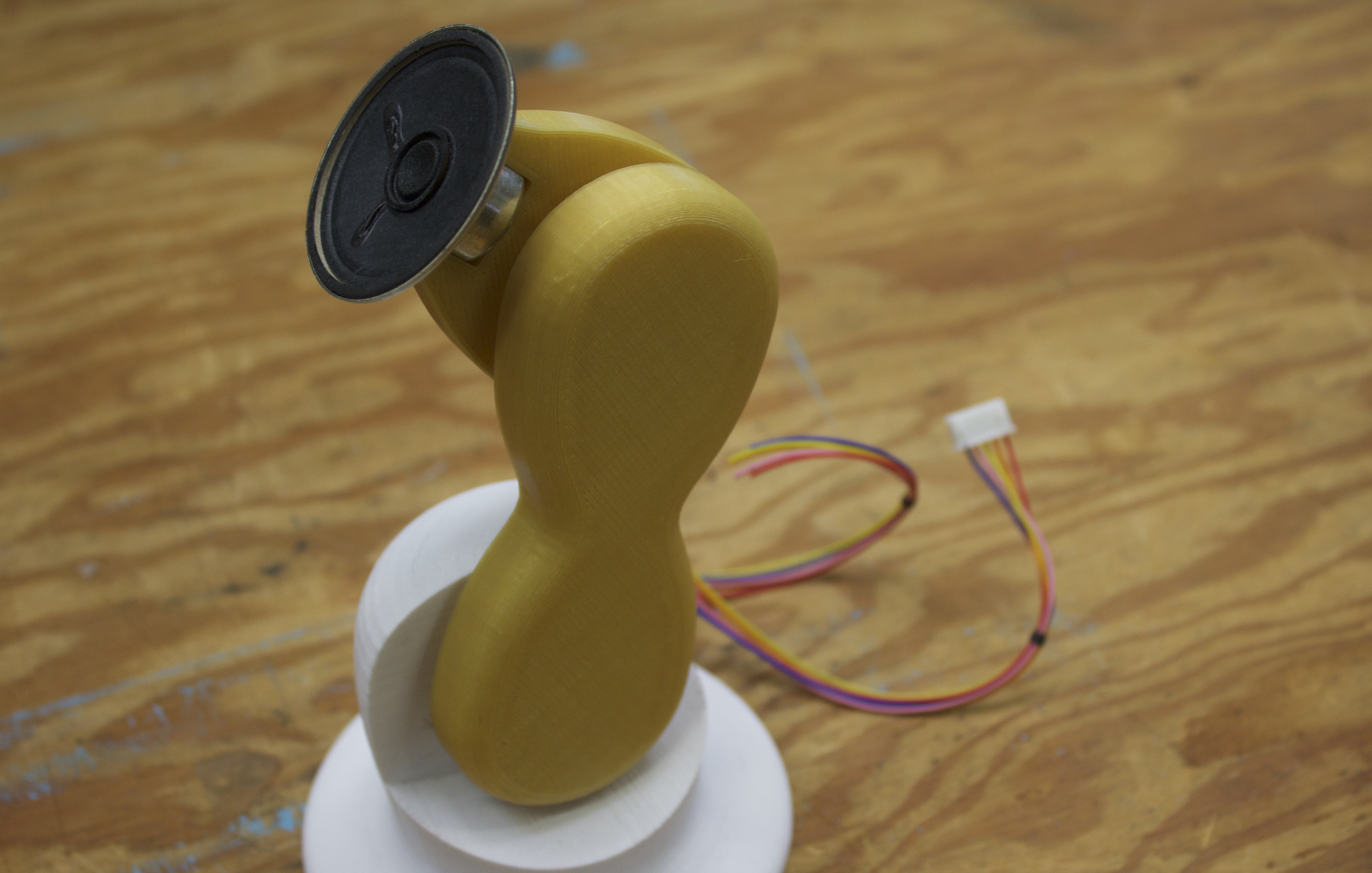
I will be mounting a small speaker, though what you choose to mount will be entirely up to you. The important thing to keep in mind is that using the 3D modeling techniques and tools that I have discussed so far in these tutorials will help you design anything in a CAD software. That means you can mount a speaker on a robot arm, or a small computer screen, or a laser pointer, or even a small hand if you design it well enough.

I am choosing to print and mount a speaker because I want my robot to be able to talk to people based off of their location to it. We will get to controlling the robot at that level after we finish designing and printing the main structure. Similarly to how the other parts of the robot are designed, we will take a step by step approach for how to create a mounting arm that will interface with our stepper motors and our parts we have already created.

The robot that we will design here will be relatively simple compared to what is possible, but keep in mind it is important to scale projects up only when we have a firm grasp on the fundamentals. Robots, and especially robots made with 3D printers, have limitations that are only defined by our imagination. Still, the more basic tools we know and practice, the better we will be at turning our ideas into real functioning robots. Eventually we will be able to turn this robot into anything we like.

What will the next generation of Make: look like? We’re inviting you to shape the future by investing in Make:. By becoming an investor, you help decide what’s next. The future of Make: is in your hands. Learn More.

Project Steps

Duplicate and scale the components

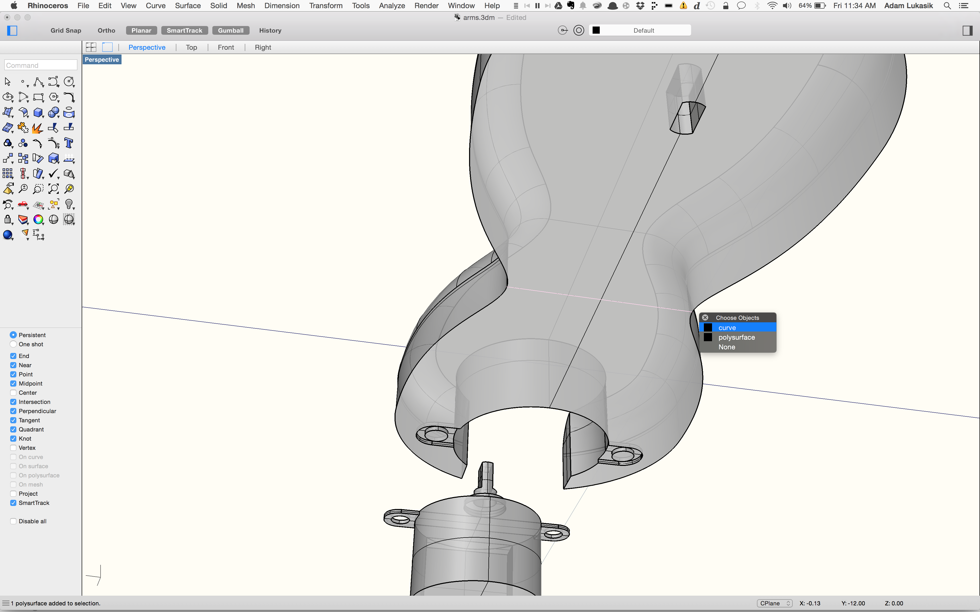
Using the files we created while working on the previous parts of the robot, we duplicate the modular arm and the motor.

Once we do that, we scale the motor up by about .005″ in each axis.

Place motor and account for wires

Next we place the motor in the arm so that the rotational element of the motor is roughly at the center of that side of the arm segment. Make sure it is flush with the bottom face, as if it was embedded perfectly inside the arm.

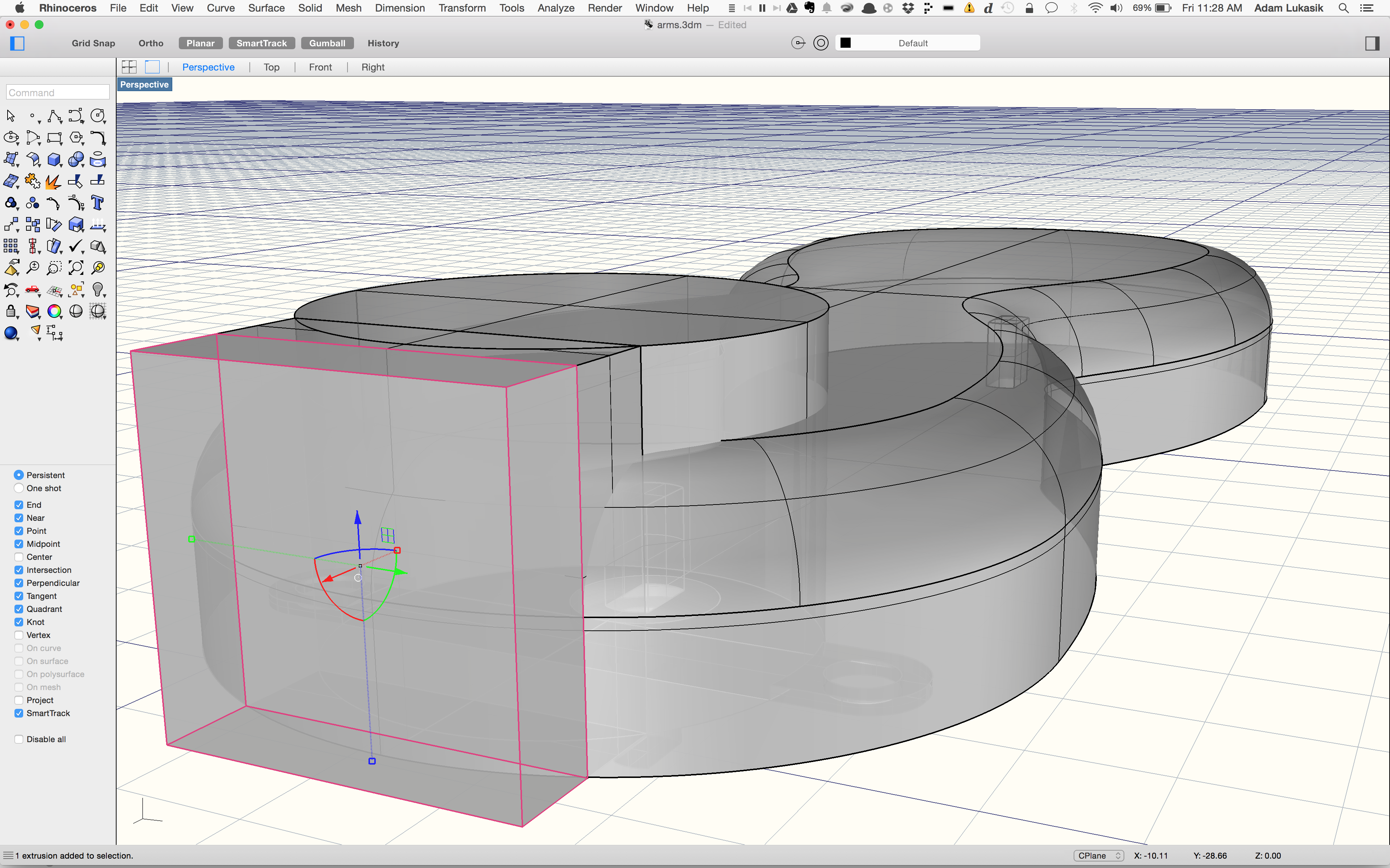
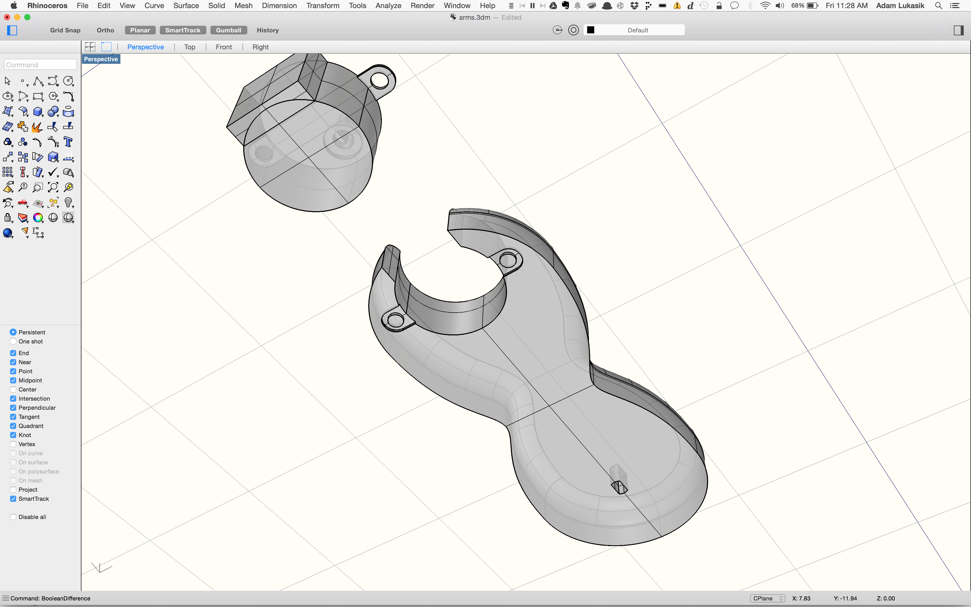
Now we will add a box that we will use to subtract from the arm on the back end of the motor to account for the wires. It is always necessary to account for the wires coming out of the motor.

Use the boolean difference command

This will function somewhat differently in all CAD software but using a boolean command to subtract one shape from another will fulfill this step.

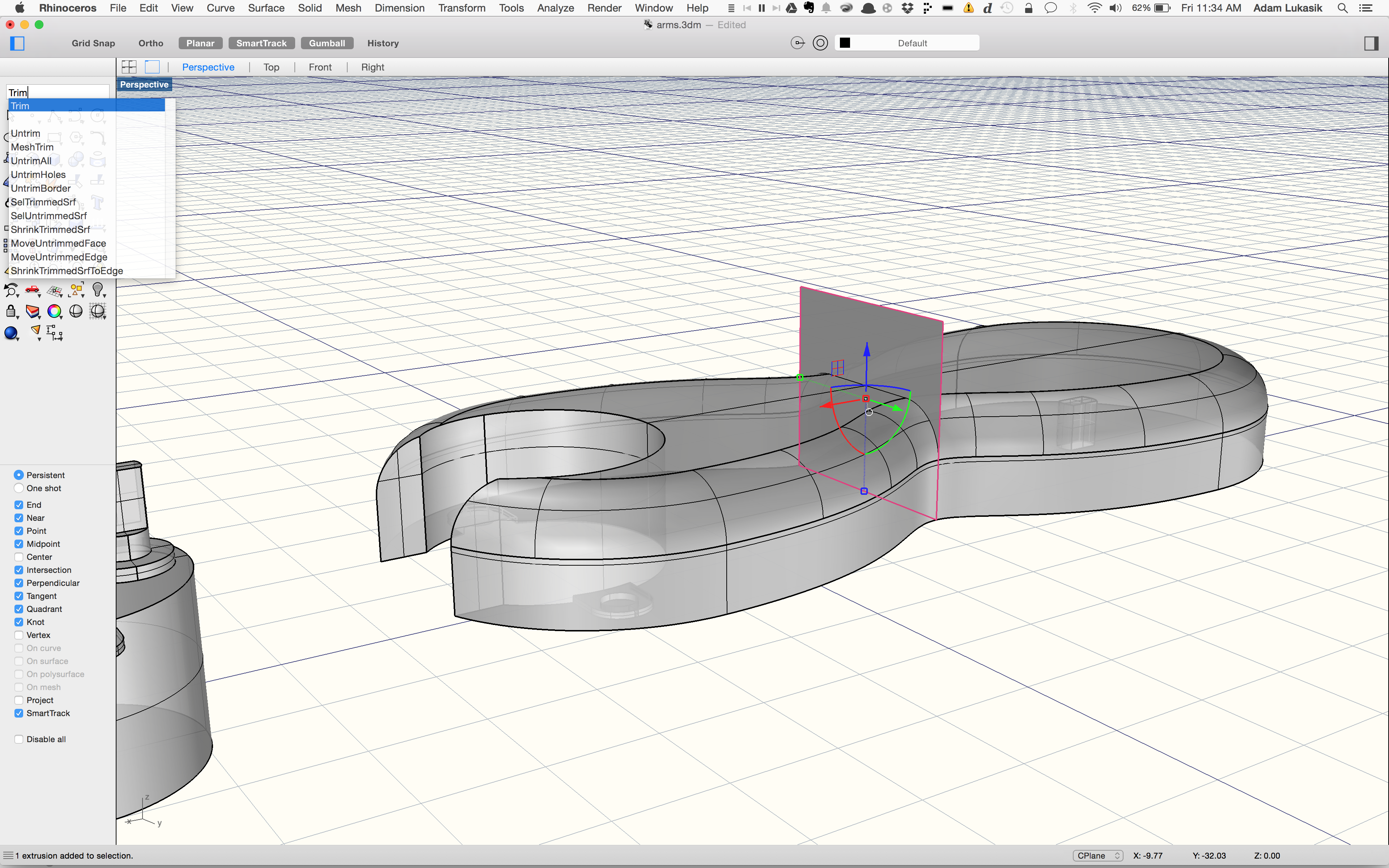
Creating a plane to trim part of the arm

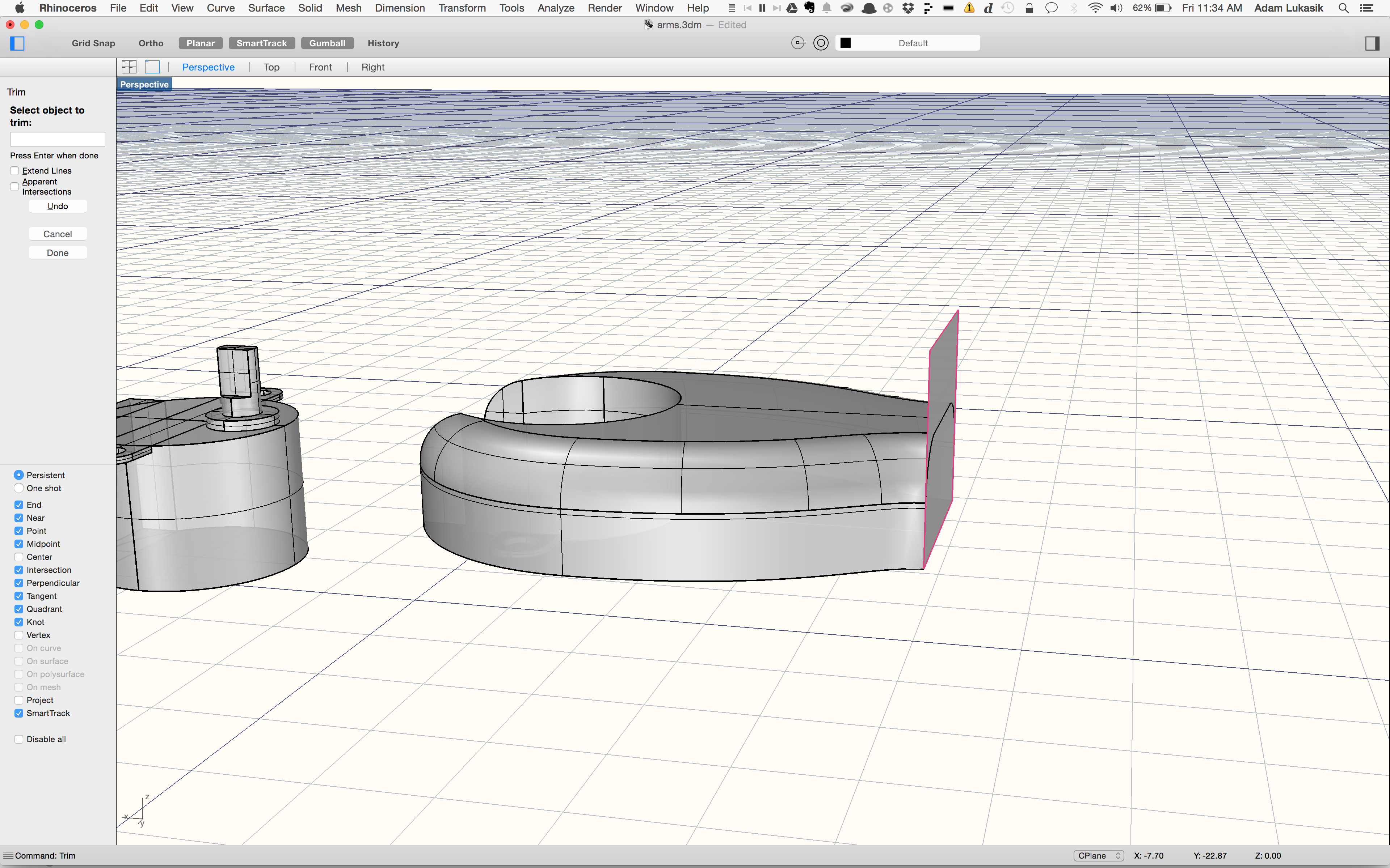
Now we create a plane bisecting the arm through the center. We do that by drawing a line, then extruding that line.

Now we use that plane to trim the arm geometry. We do this to remove excess material that would add unnecessary weight.

Add the geometry for the speaker

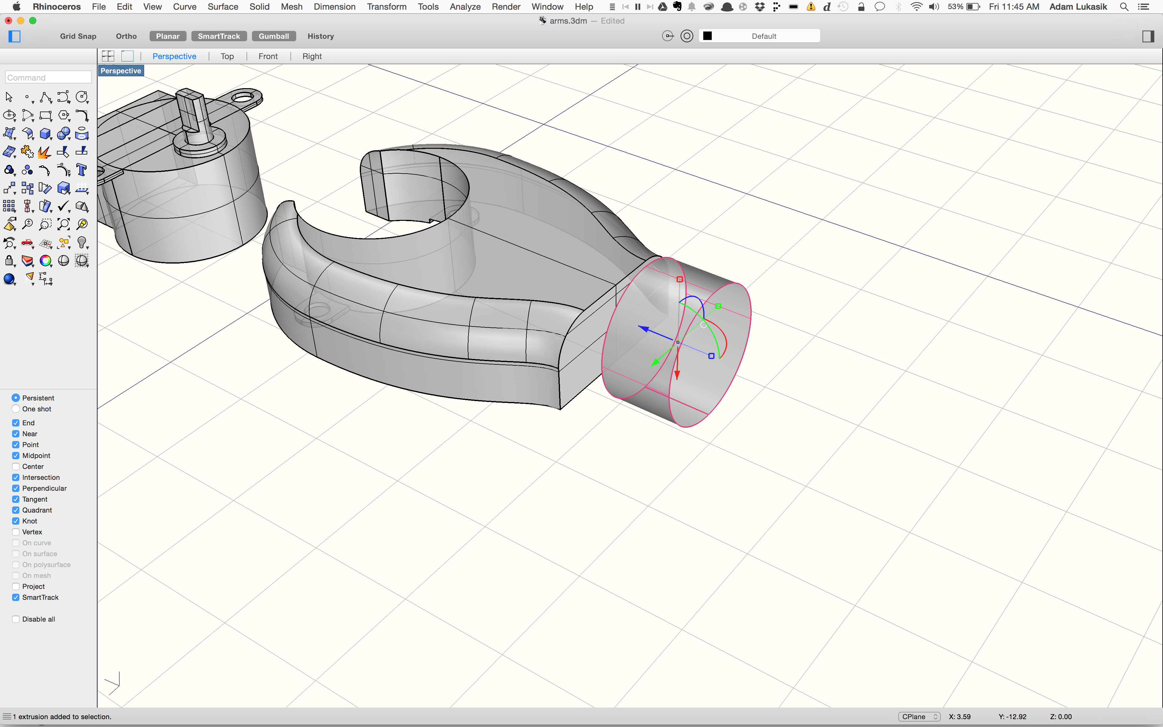
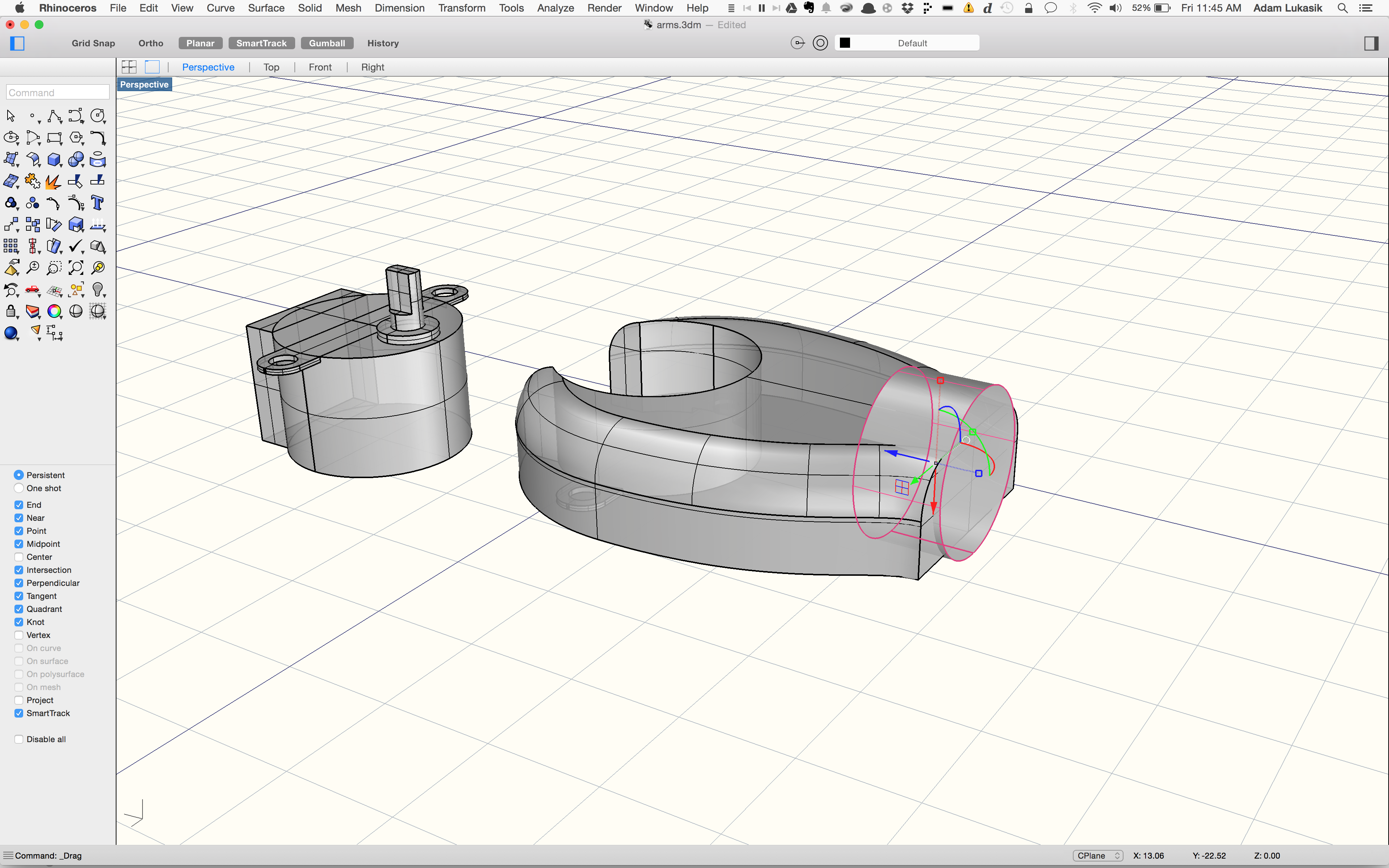
As I said in the intro, what we mount to the arm can be easily changed through different steps at this stage in the design. I want to add a speaker to mine so we will step through that process. Using calipers I measured the cylinder magnet at the base of the speaker and modeled that cylinder.

I then used another boolean subtraction command to remove the shape of the speaker’s base from the mount segment.

Export and print!

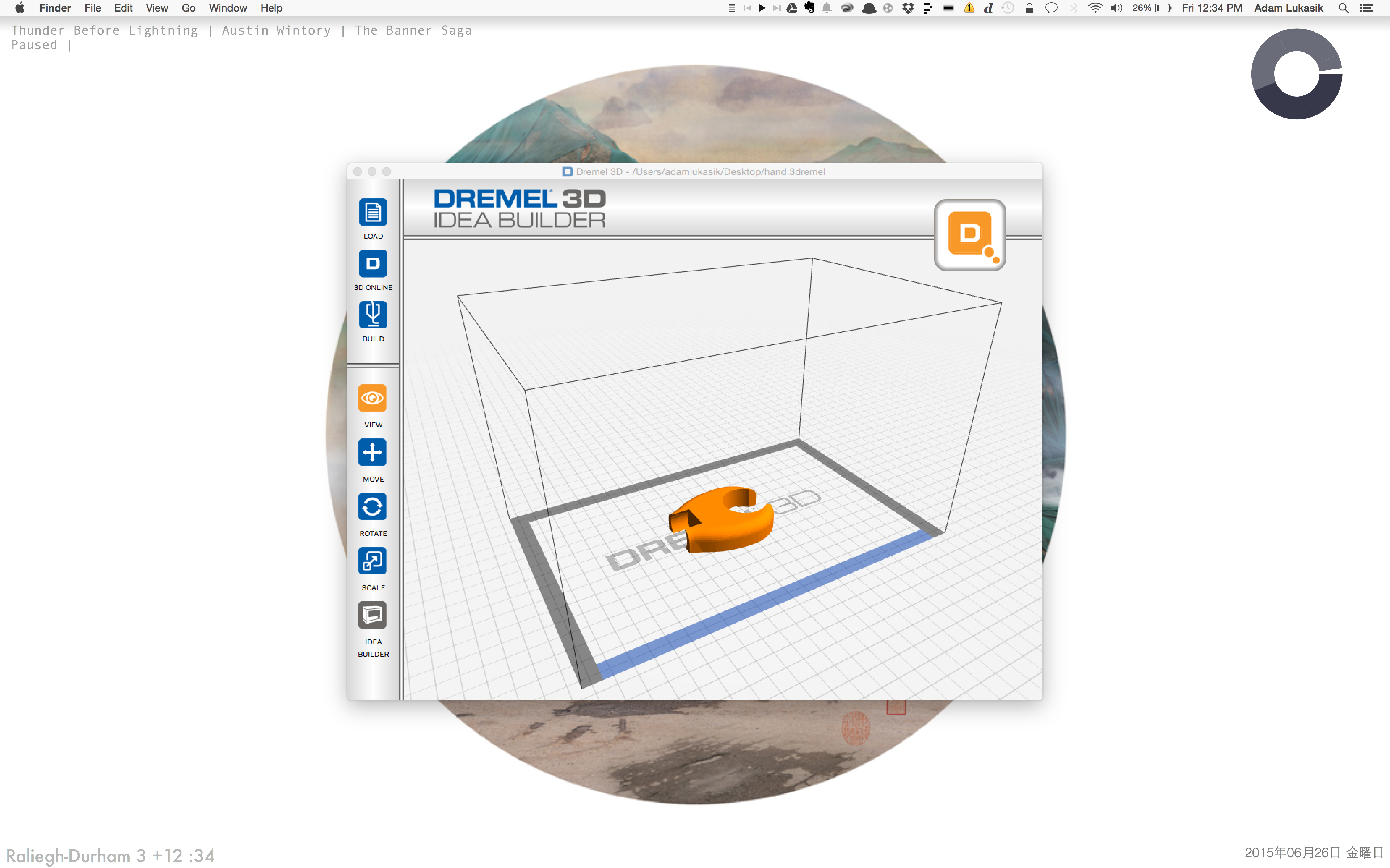
Finally we export the mount segment and load it into our slicer to print. Again I am using the Dremel Idea Builder to print this.

Assemble

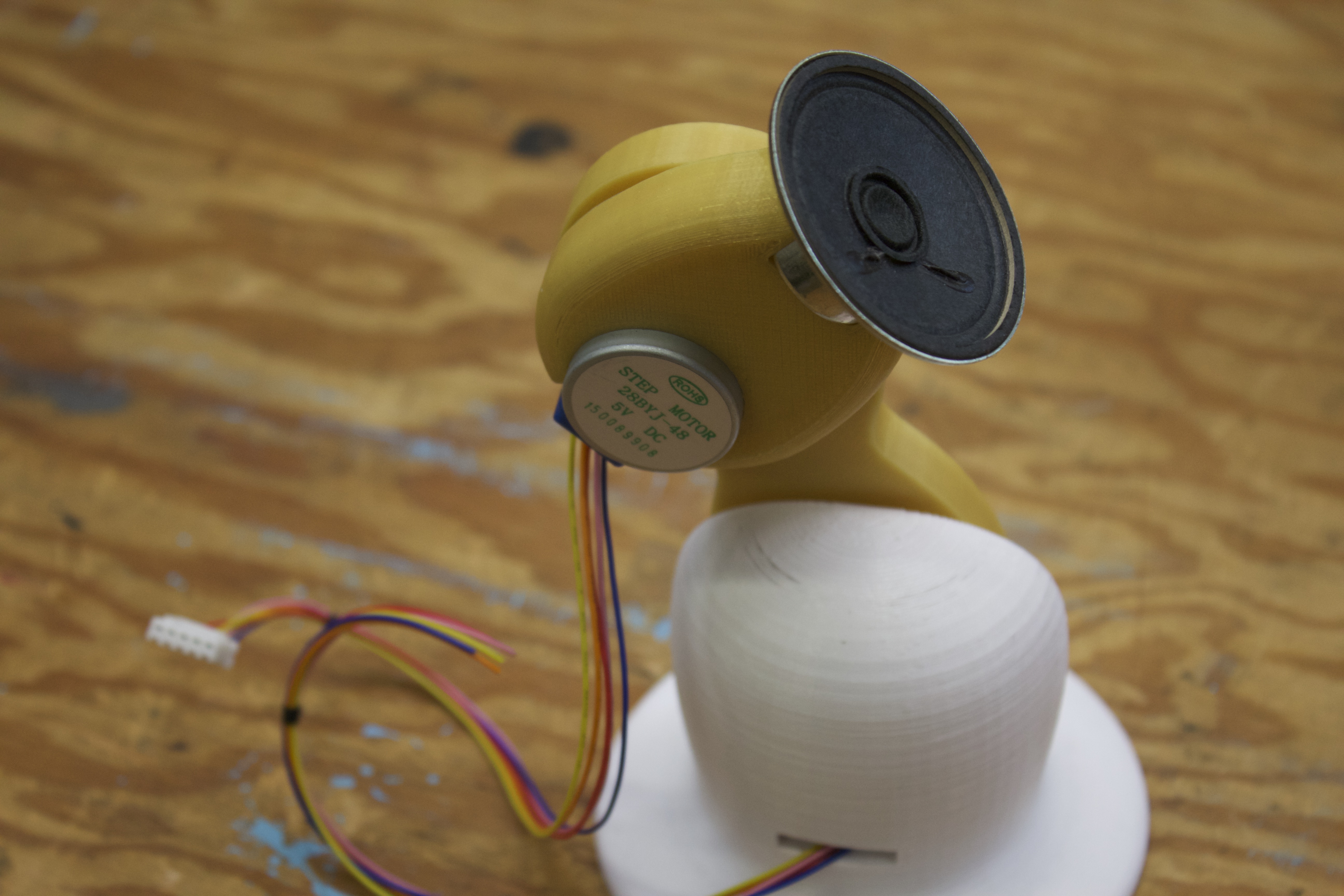
Once the piece is printed we assemble all of our custom component parts into a complete 3D printed robot arm!

Conclusion

Now that we are finished designing our custom 3D printed robot arm, we can explore how to control it. In the final section of this exploration of custom robotics we will go over how to control the robot arm using raspberry pi and python. The skills that are discussed in this project and the previous two projects are tools that can be used to design and model almost any objects and turn them into real, usable pieces. I encourage you to explore and practice through your own interests, and as always feel free to post questions and comments and email me.