TimeLapse-6

If you dig around in your camera’s settings long enough, you’re almost assured to find that it has a mode to create time-lapse videos — those magical, time compressing movies that can turn any hillside or street corner into a lightning-paced dreamscape.

Time-lapse videos by themselves are easy enough to make, but if you do enough of them, you’re likely to get bored with the motionless camera framing. But what can you do here? Having a moving time lapse means moving a camera very predictably, and very, very slowly. You can build a simple panning rig out of a mechanical kitchen timer, but that’s only good if your time lapse is an hour or less, plus, the camera will rotate the full 360 degrees in that hour, further limiting your control.

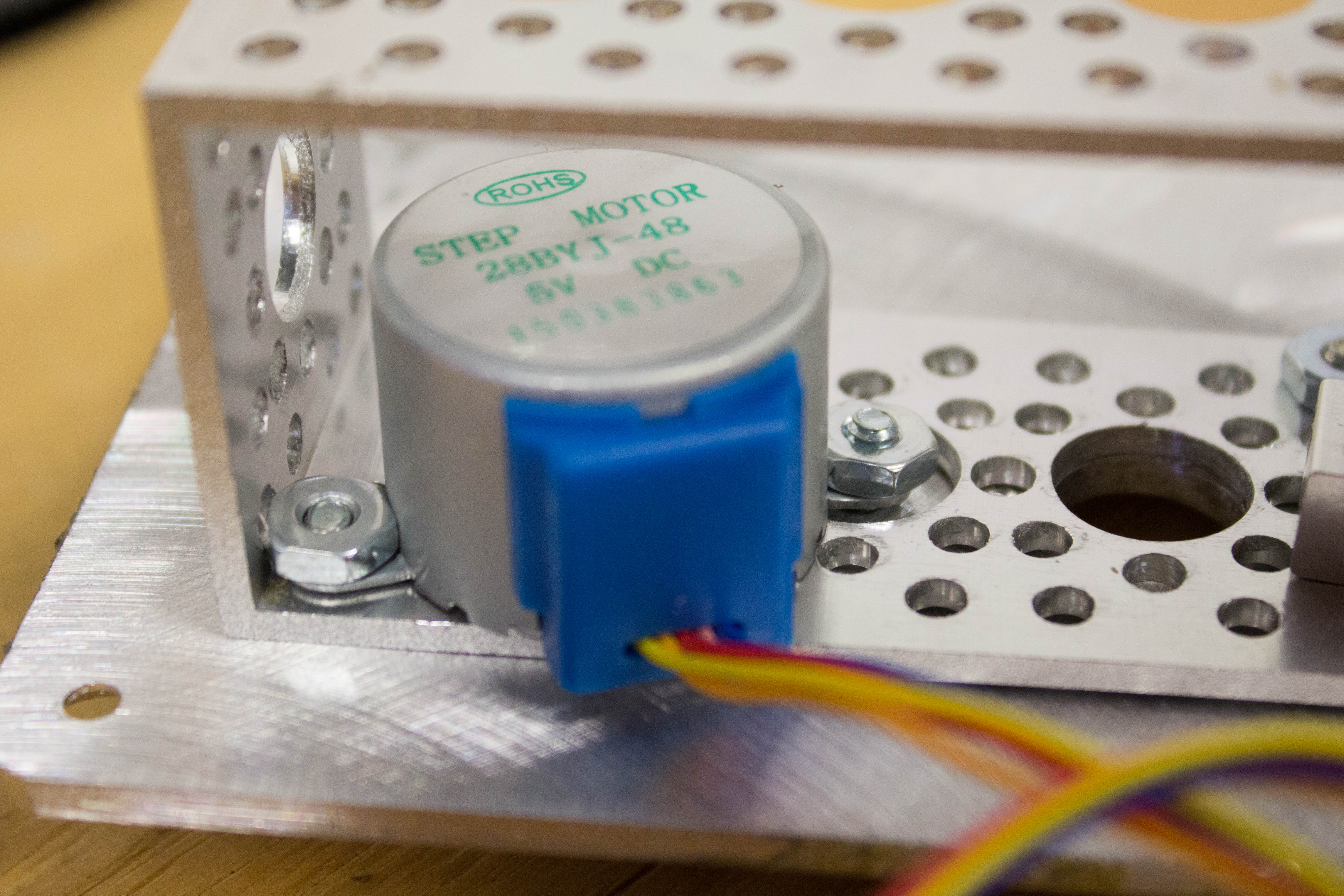
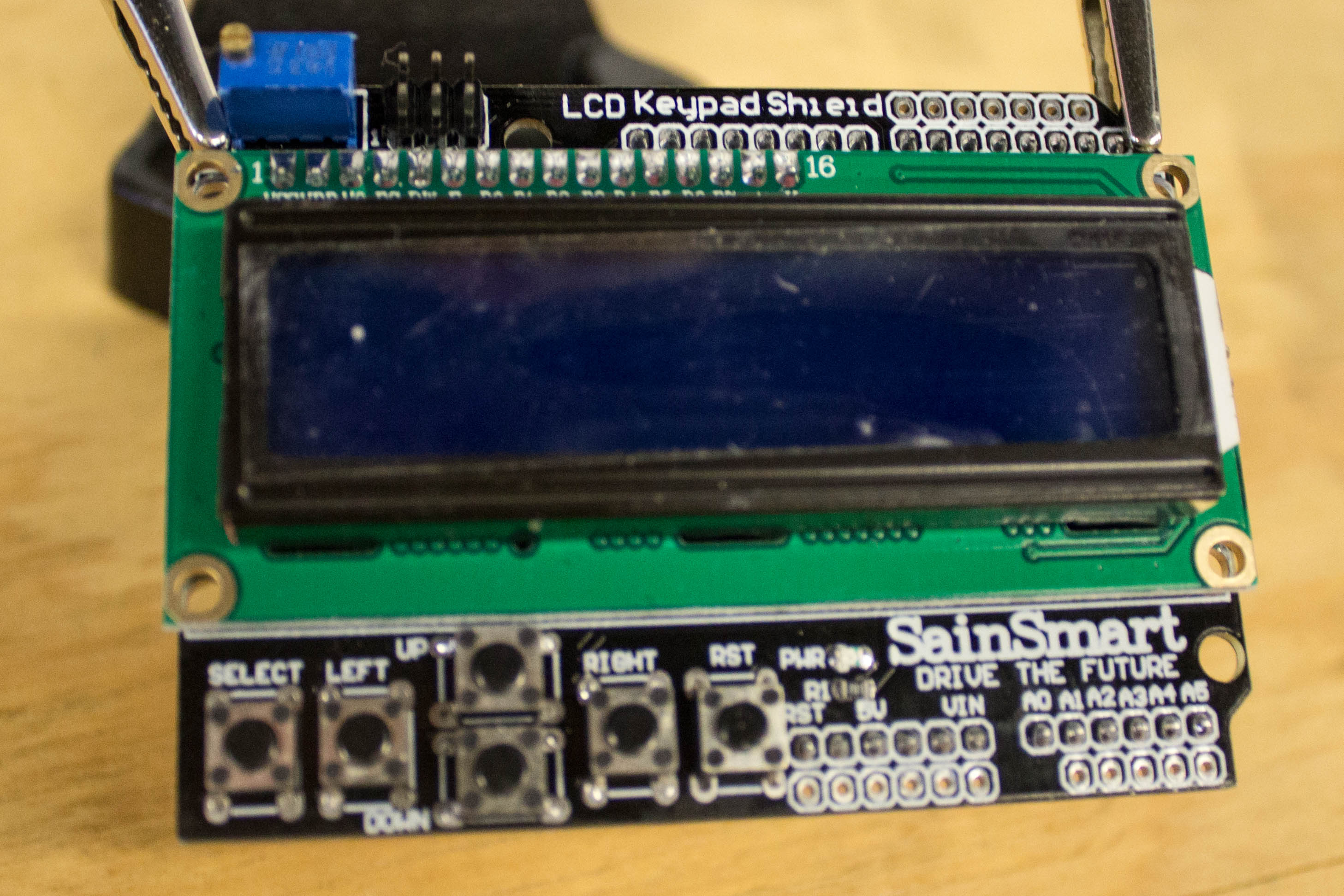
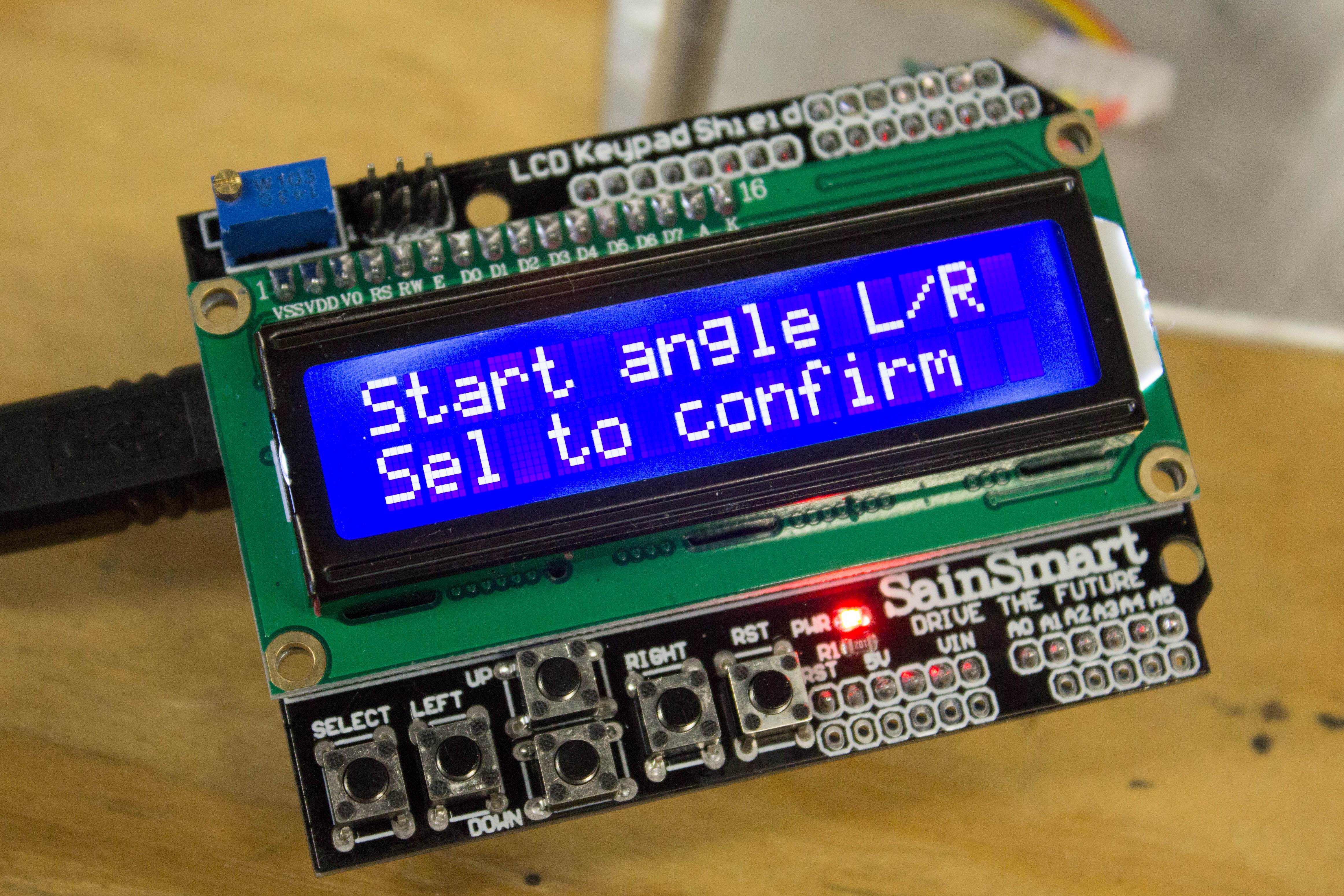
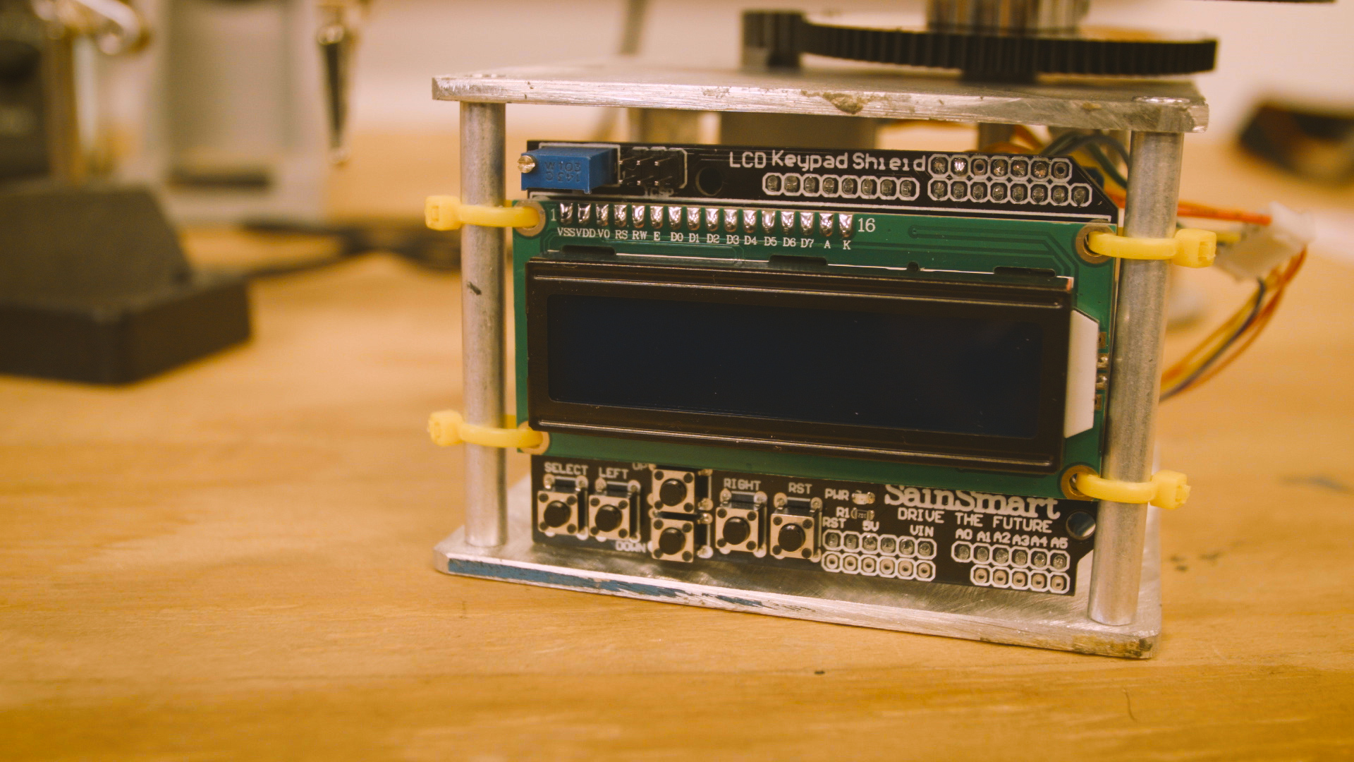
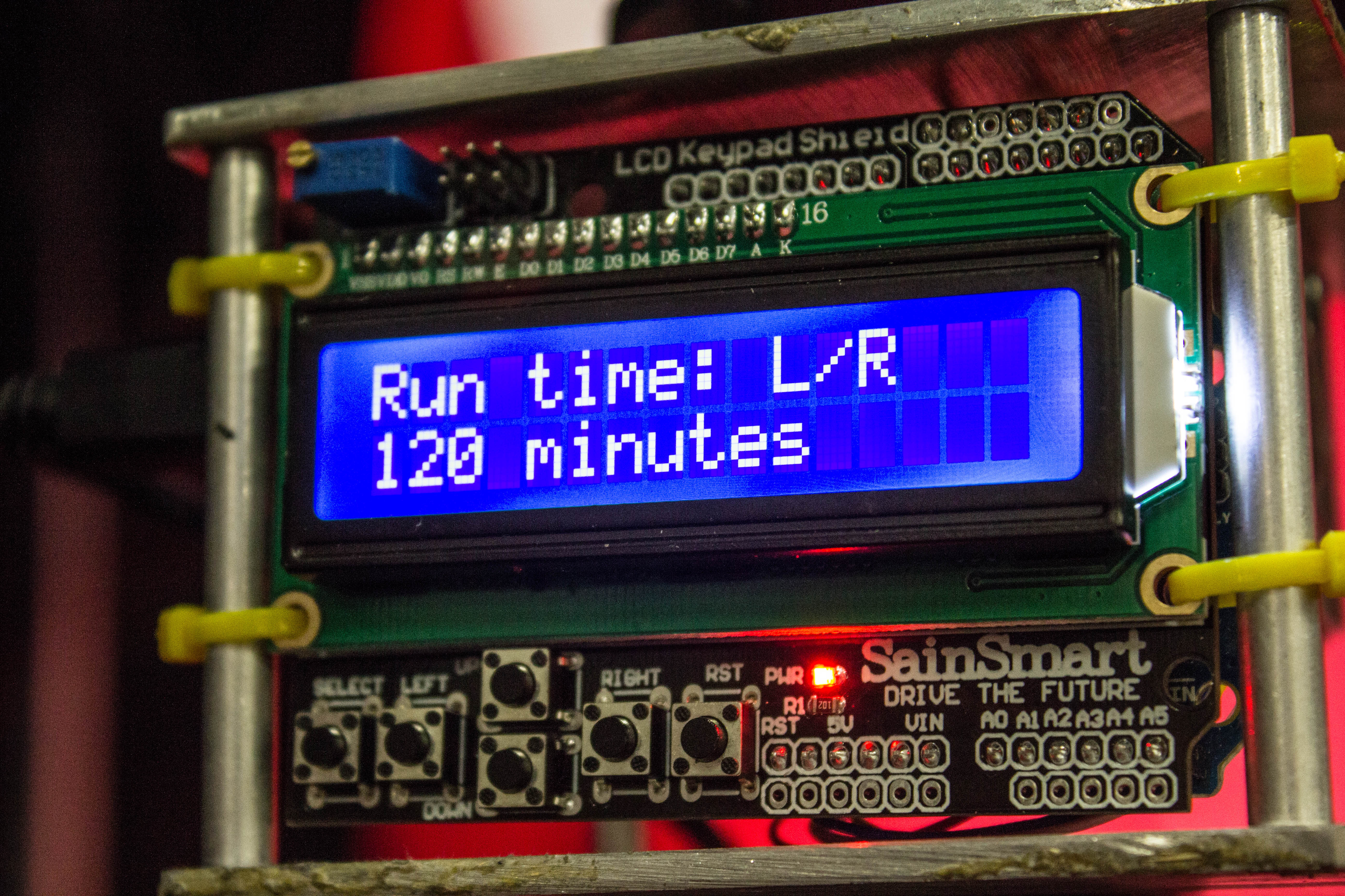
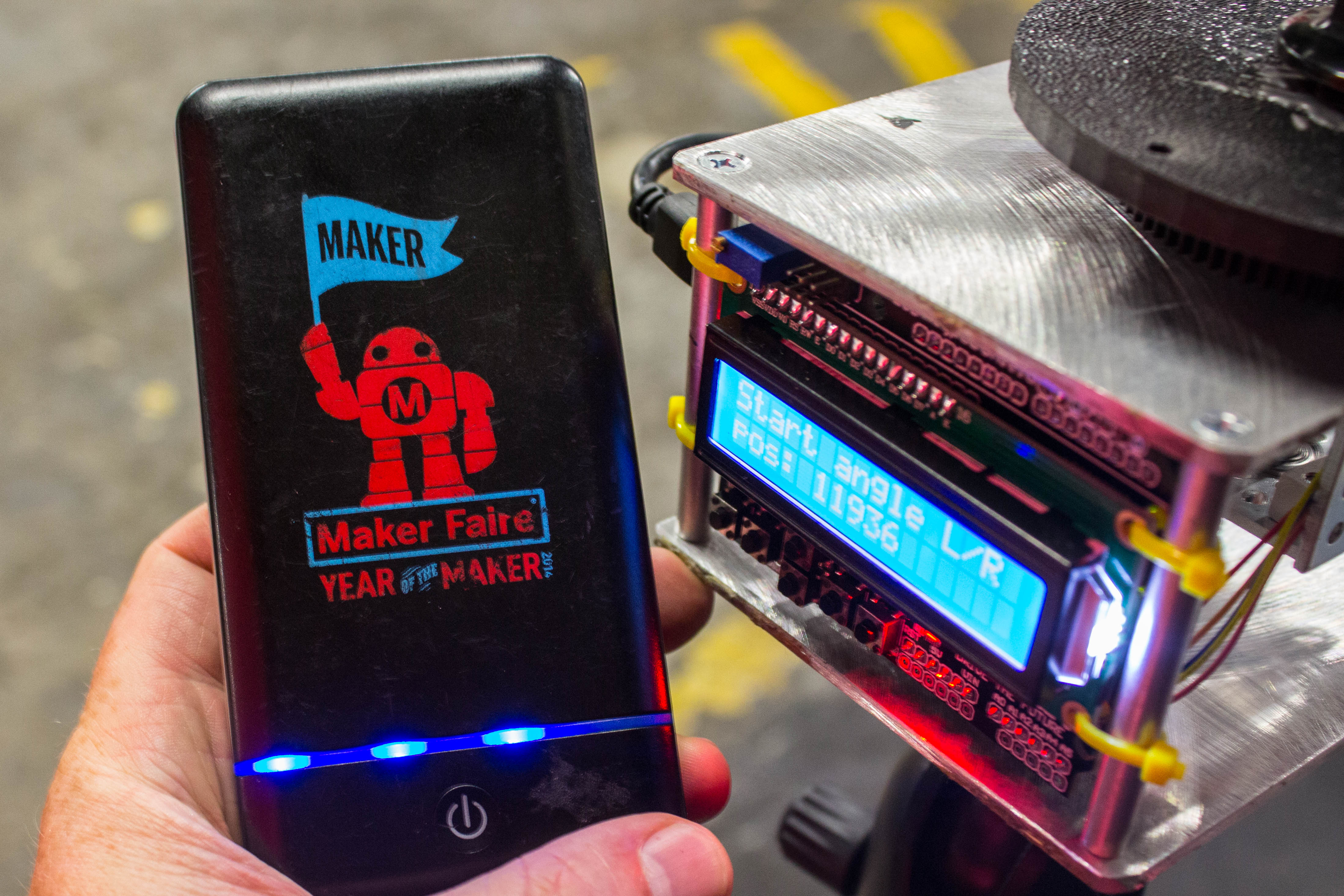
In this project, we’ll be using an Arduino microcontroller and a stepper motor to precisely control the panning of a camera during a time lapse. Using this LCD keypad shield as an interface, we can precisely set our starting and stopping positions, as well as setting the duration of our time lapse — anywhere between five minutes and 12 hours. The device can be powered via any USB power source, and those portable USB bricks used to keep your smartphone alive during long days will work perfectly, and can power the device for up to 12 hours.

Project Steps

Prepare the chassis plates

We’ll begin by drilling holes into the top and bottom plates that make up the chassis. Start by cutting your aluminum bar stock into two 4”×4” squares and sand down any burrs or rough edges.

Precision drilling matters here, so print out the provided drilling template and apply it to the two squares using contact adhesive, and if you have access to a drill press, use that to drill the holes.

Countersink all of the ⅛” holes drilled, and tap the hole in the center of the bottom plate with ¼ – 20 threads. Remove the templates and any remaining glue residue.

Build the drive sub assembly

Next we’ll begin building the sub assembly that will hold the stepper motor and the driven shaft. Use the two connection blocks and four 6-32 flathead screws to find the best holes to assemble the block, and then countersink those holes so the screws are flush with the surface.

Mount the stepper motor

Attach the pinion gear to the drive shaft of the motor and secure it with the set screw. Mount the stepper motor into the channel assembly and to the top plate using three flathead 6-32 screws and nuts.

Make sure the shaft of the stepper motor is centered in the ½” hole on the right side of the channel. Place bearings into the bottom of the channel and into the top plate of the assembly. It’s not necessary, but you can use threadlocker to help secure the bearings in place.

Complete the chassis

It’s a good time to complete the rest of the chassis. Attach the four threaded rods to the top plate using flathead screws, and then attach the bottom plate to the same rods with another four screws.

Build the driven shaft

Prepare the driven gear and the servo mount by countersinking a pair of holes into each of them.

Use flathead screws to mount them to opposite sides of the clamping collar, ensuring the screw heads are flush with the surfaces, and then secure the collar to the shaft.

Insert the shaft into the bearings, making sure gears are meshing well. Once a good fit is achieved, prepare some JB weld. Fit the cap screw into the hole in the servo mount with the threads pointing up, and then secure the screw into place with JB Weld. Once cured, check the mounting clearance with your camera. If the screw is too long, trim off the excess.

Wiring the keypad shield

We’re nearly ready to wire up the Arduino, but first we need to prepare the keypad shield to get access to some of the additional pins to drive the stepper.

Cut and strip 5 equal lengths of jumper wire, using colors that most closely match the ribbon cable of the stepper motor. Solder the jumpers to the underside of the keypad shield using this placement.

Fit the stripped ends of the wire into their corresponding colors of the motor’s wiring harness. Fit the keypad shield onto the Arduino.

Programming the Arduino

Download the sketch.

Connect the Arduino to your computer via a USB Cable, and upload the sketch. Once loaded, use the left and right buttons on the keypad to change the rotation of the camera.

Check to make sure the camera platform is able to complete a full rotation. Once everything looks great, use zip ties to attach the keypad shield to the rods using the mounting holes.

Capturing a time lapse

You can attach just about any camera to the top plate using the 1/4 – 20 stud, and the motor should be strong enough to carry a lightweight dSLR.

Once you have your time lapse set up on the camera, set up the panning on the Arduino. Set your start angle, and then your finishing angle, and then decide how long you want the program to run.

After you confirm the time, the program will run. You can power the device from any USB power source, or a portable USB battery.