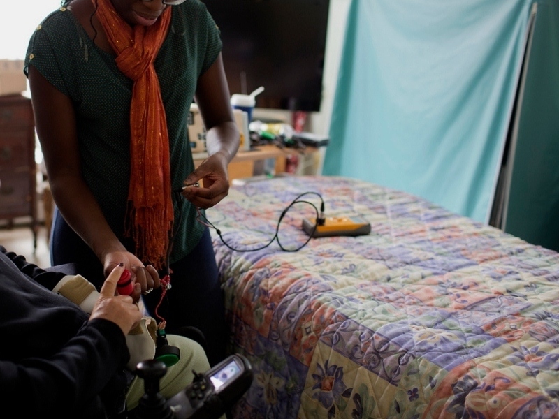
Our client was an individual with multiple sclerosis, an autoimmune disease that targets the covering on the axons of neurons, damaging connections to the brain and spinal cord. Our client uses a wheelchair as a form of mobilization around the room. For assistance purposes, it is necessary to have some sort of system for the resident to be able to contact the physician. The system we have developed can use either buttons or voice activation to initiate the call. This allows for flexibility so that patients with different impairments are able to use the system with ease.

Project Steps

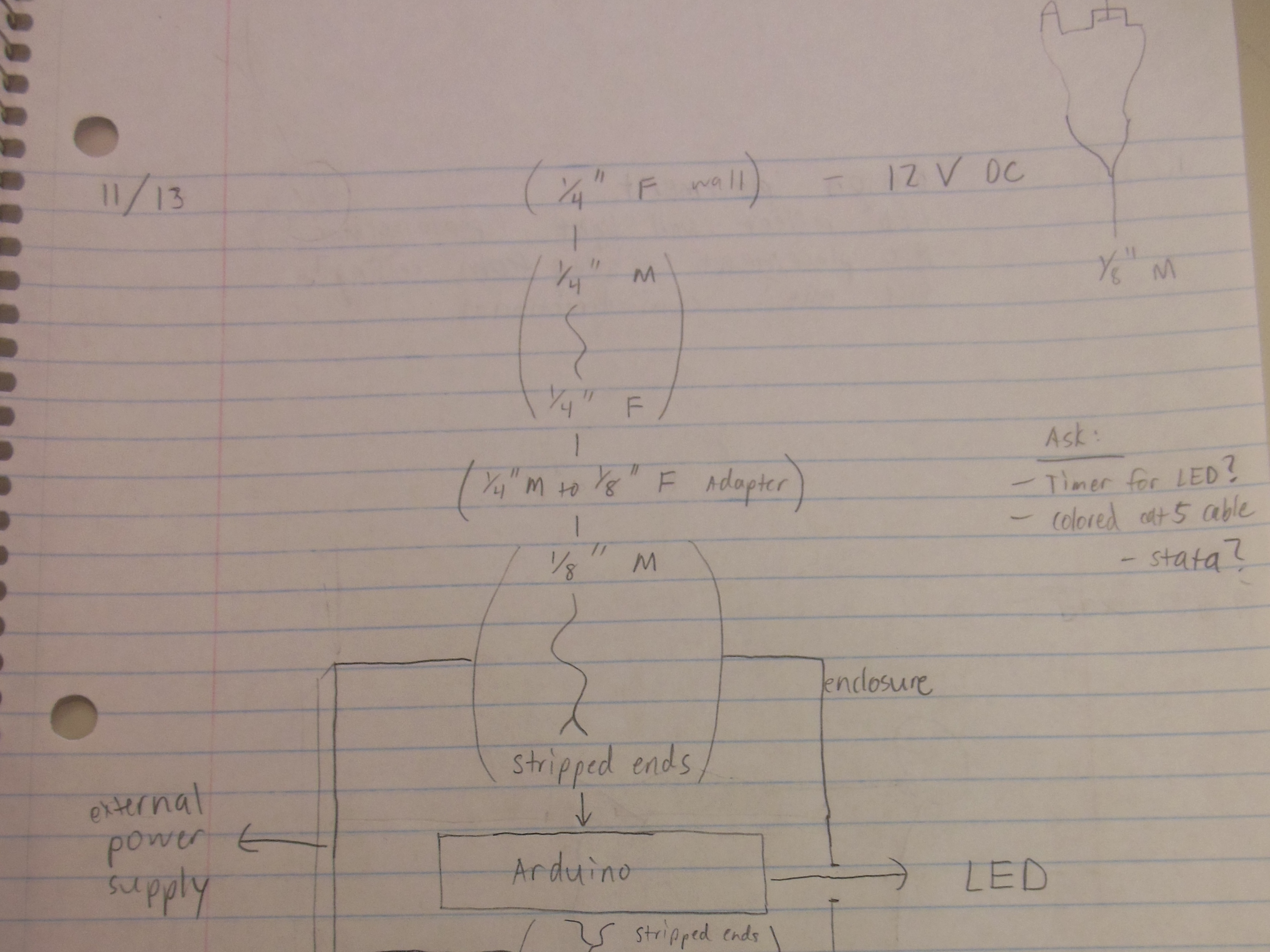
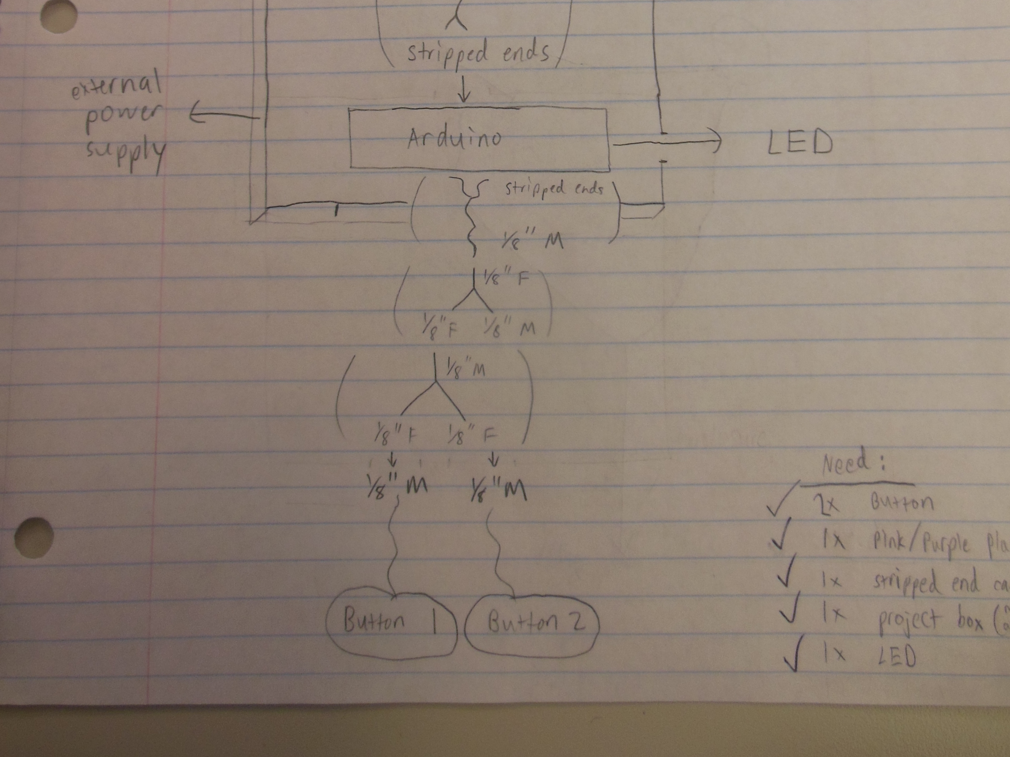
Map out the electric flow of the system from the wall to the button.

This system supplies a constant power source and uses a pushbutton switch to close the circuit to the wall, activating the nurse call.

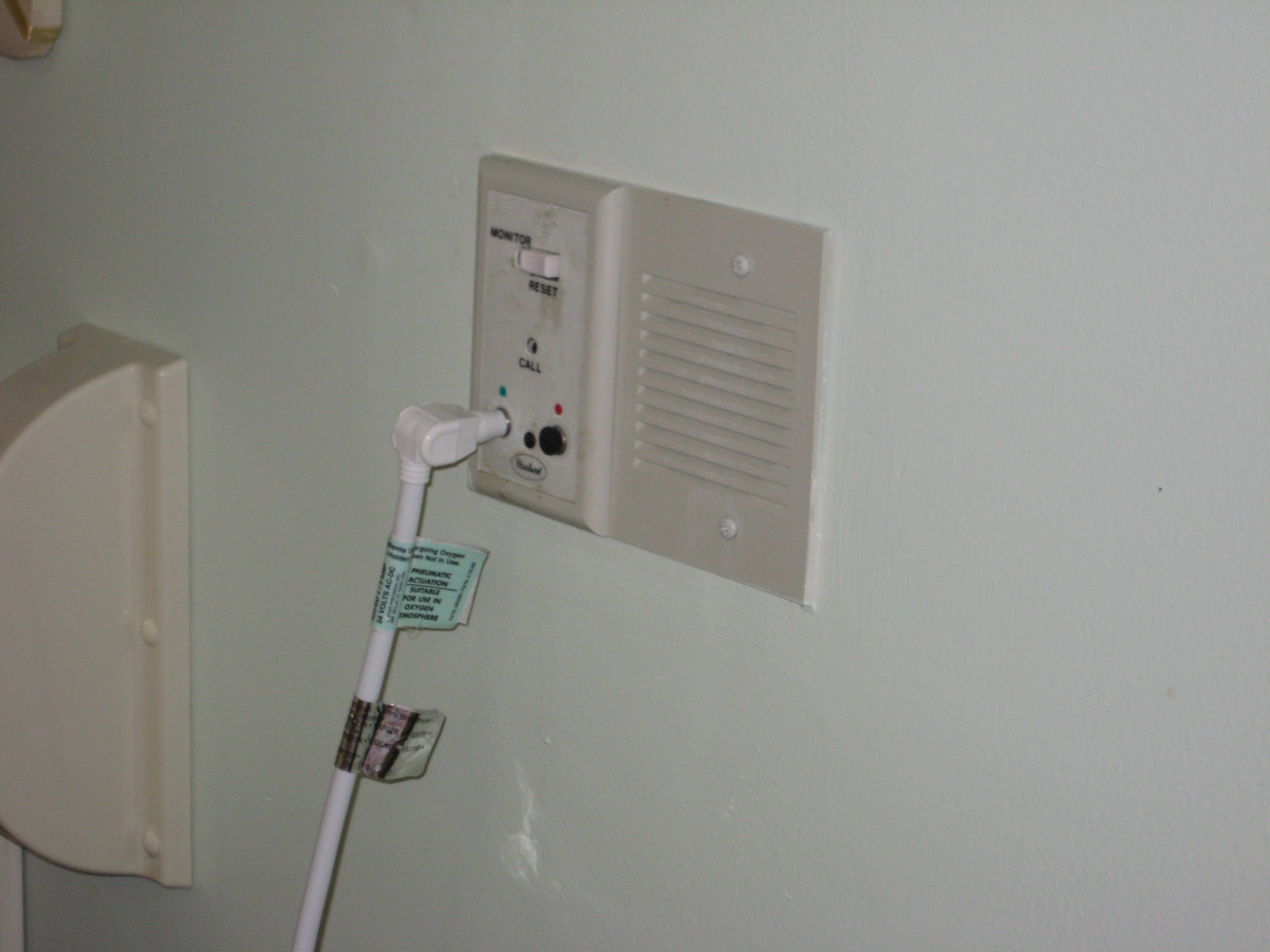
Record the type of connector at the wall.

Wall: 1/4″ female mono jack

Using a multimeter, measure the voltage coming from the wall (~12V in this case).

From the wall, connect:

Wall to 1/4in male-female mono extension cable to 1/4in to 1/8in mono adapter to 1/8in male to stripped ends mono cable to Arduino pin. This will be the wall-socket line connecting to the nurse call jack.

For the new pushbuttons, connect:

Button #1 to 1/8in male-female mono Y-adapter #1 to 1/8in male-male mono cable to 1/8in male-female mono Y-adapter #2 to 1/8in male-female mono Y-adapter #3 to 1/8in male to stripped ends mono cable to Arduino pin. This is the micro-switch line connecting to the push buttons.

Button #2 to 1/8in male-female mono Y-adapter #2. This is simply a second pushbutton wired in parallel with the first.

Test your button’s circuit-closure ability by connecting it either to a power supply and indicator light or simply a multimeter. To test a multiple-button setup, connect the buttons in parallel.

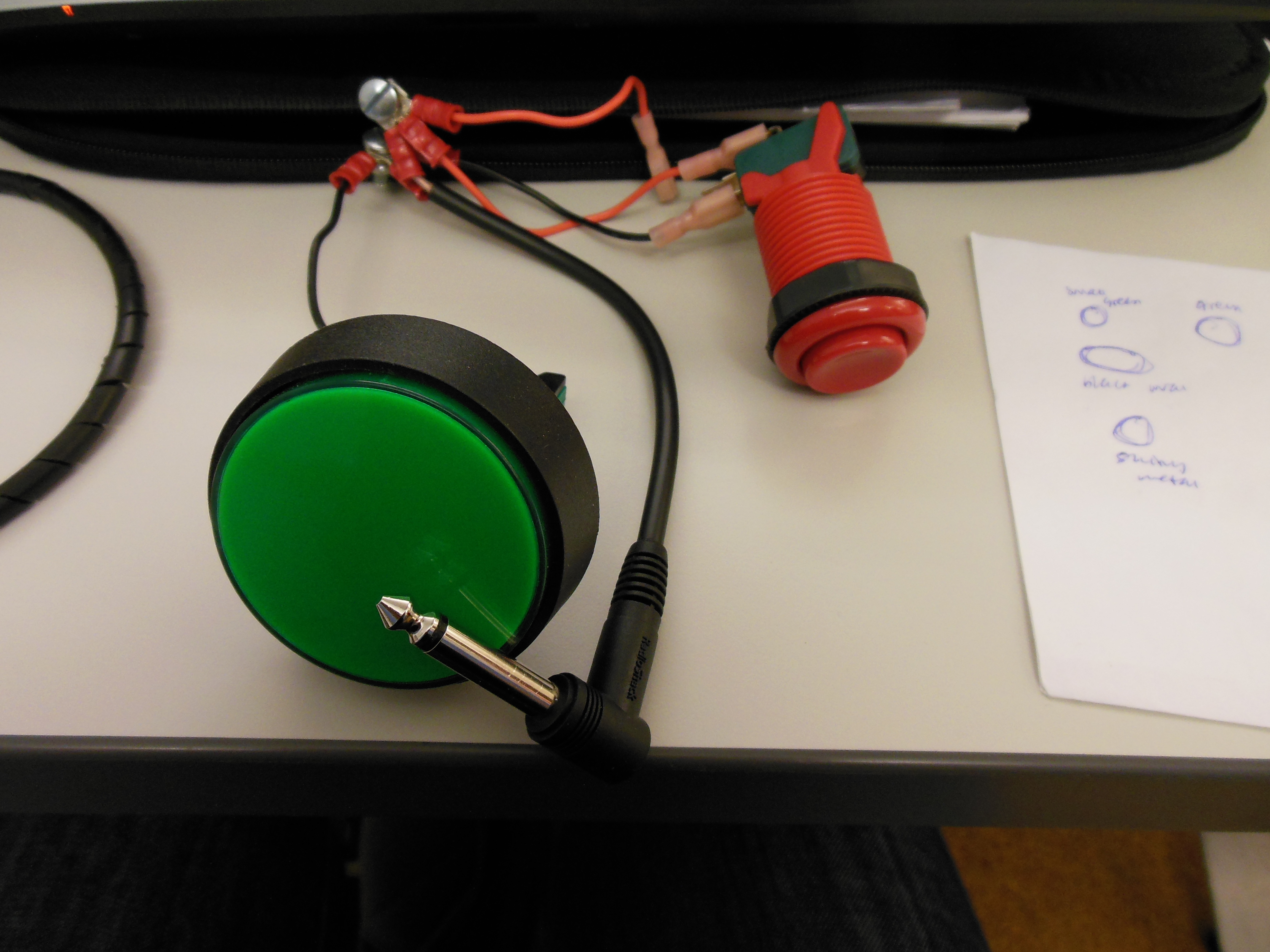
Test out a variety of buttons, and use the ones that best fit the client’s needs. Factors to consider:

Button activation pressure

Size

Shape

Color

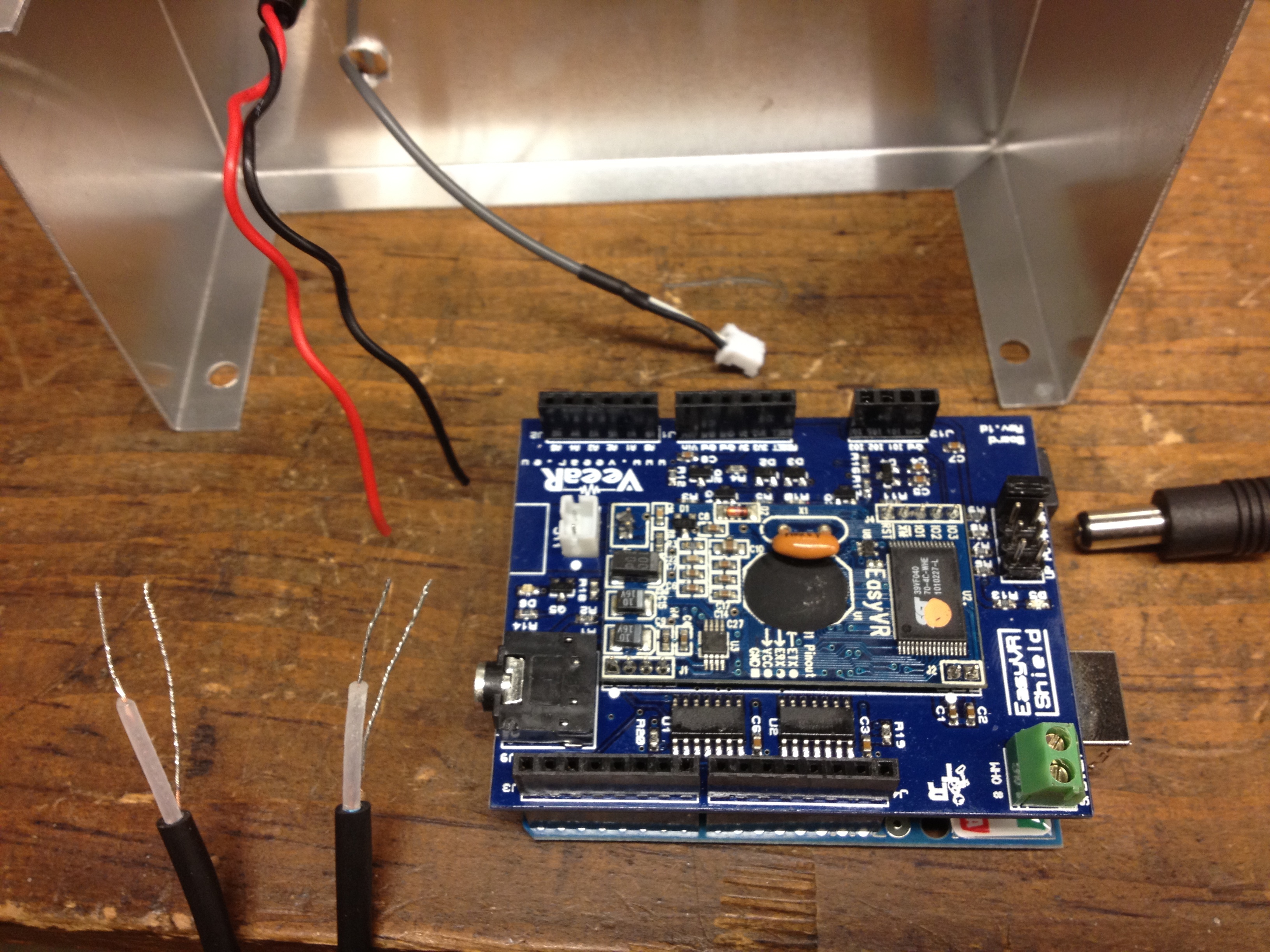
The EasyVR shield comes with software called “EasyVR Commander”, which is a graphical interface on your computer that lets you train and test voice commands.

The tutorial EasyVR Tutorial will give you step-by-step instructions on how to use EasyVR Commander to train the Arduino to respond to your voice. At the end of the tutorial, you’ll have a basic outline of code that listens and responds to voice commands.

When training on your client, remember to train in an environment similar to the one in which the system will be used.

In the next step we’ll customize the code to listen for button presses, control the LEDs, and trigger the nurse call system.

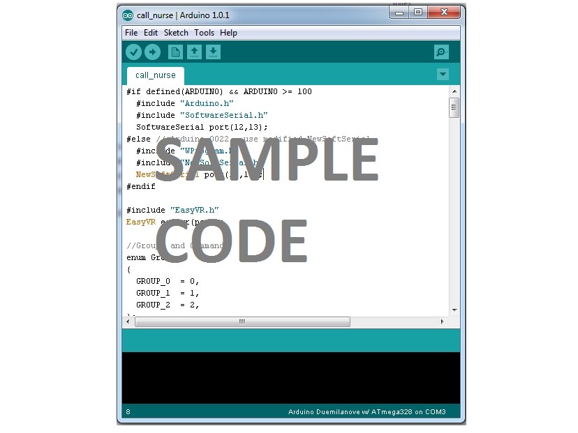
The code we used is hosted on GitHub. It looks very similar to the code you generated in the previous step.

You cannot simply copy and paste our code because EasyVR Commander generates different code for different users’ voices.

The code is short. Go through our code and look for lines labeled with // call-aid. These lines will show you the changes you need to make to your code to get it to respond to your client’s voice.

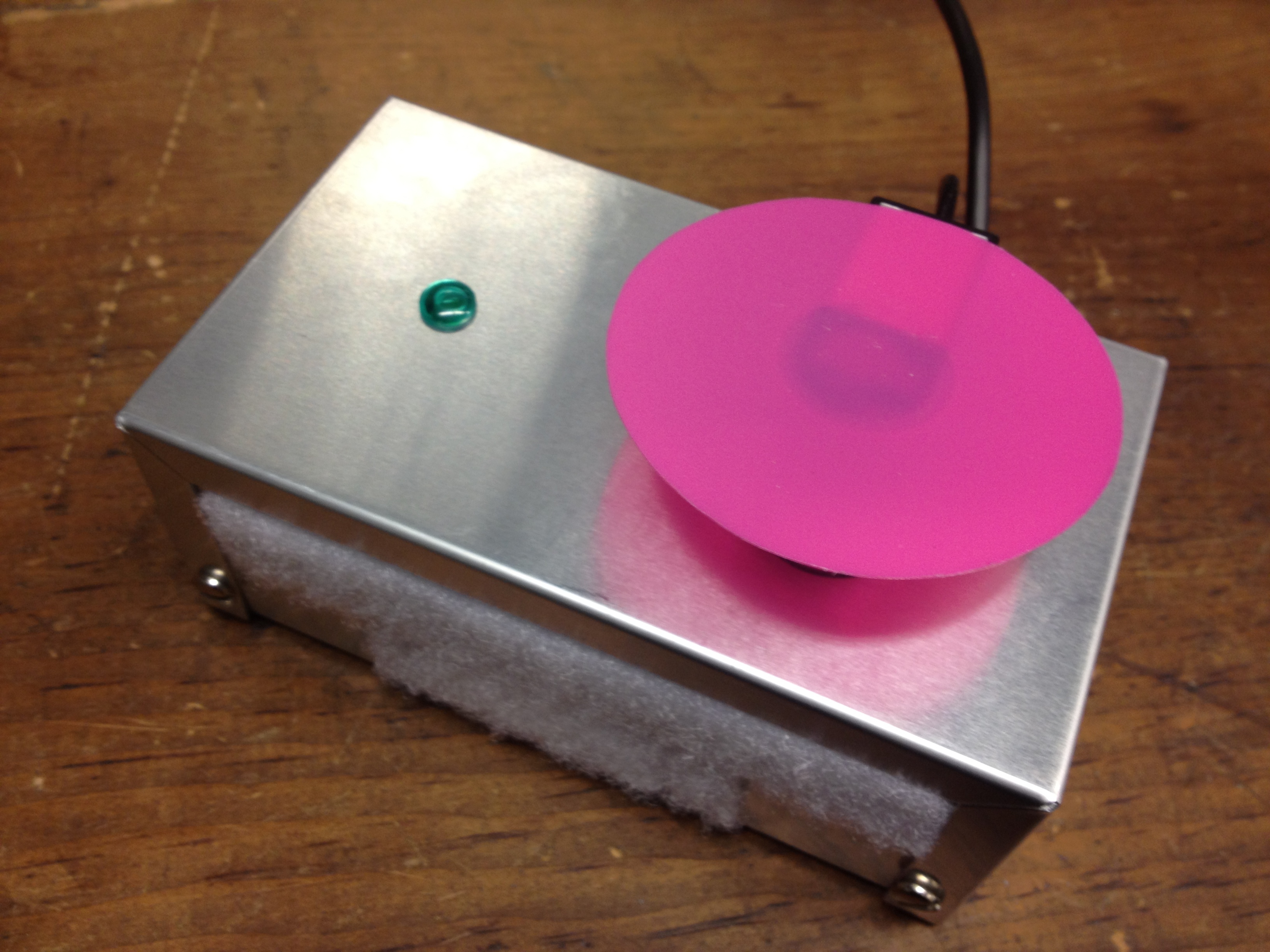
Make or purchase two 5.25in x 3 in x 2.125in project enclosures.

Box 1: Drill a hole to mount the LED and two other holes for the micro-switch “in” and “out” lines. Solder the LED in series with the micro-switch so that it lights up when the button completes the circuit.

Box 2: Drill holes for the LED, micro-switch line, wall-socket line, Arduino power supply line, and microphone.

Connect the Green LED Gnd to Pin D1 and Pwr to D0.

Connect the Button Gnd to D13 and Pwr to D10.

Connect the Wall Pwr to D4 and Gnd to D7.

Connect the power supply to the Arduino.

For testing, make sure to find the most ideal location in the room to place the system. Considerations:

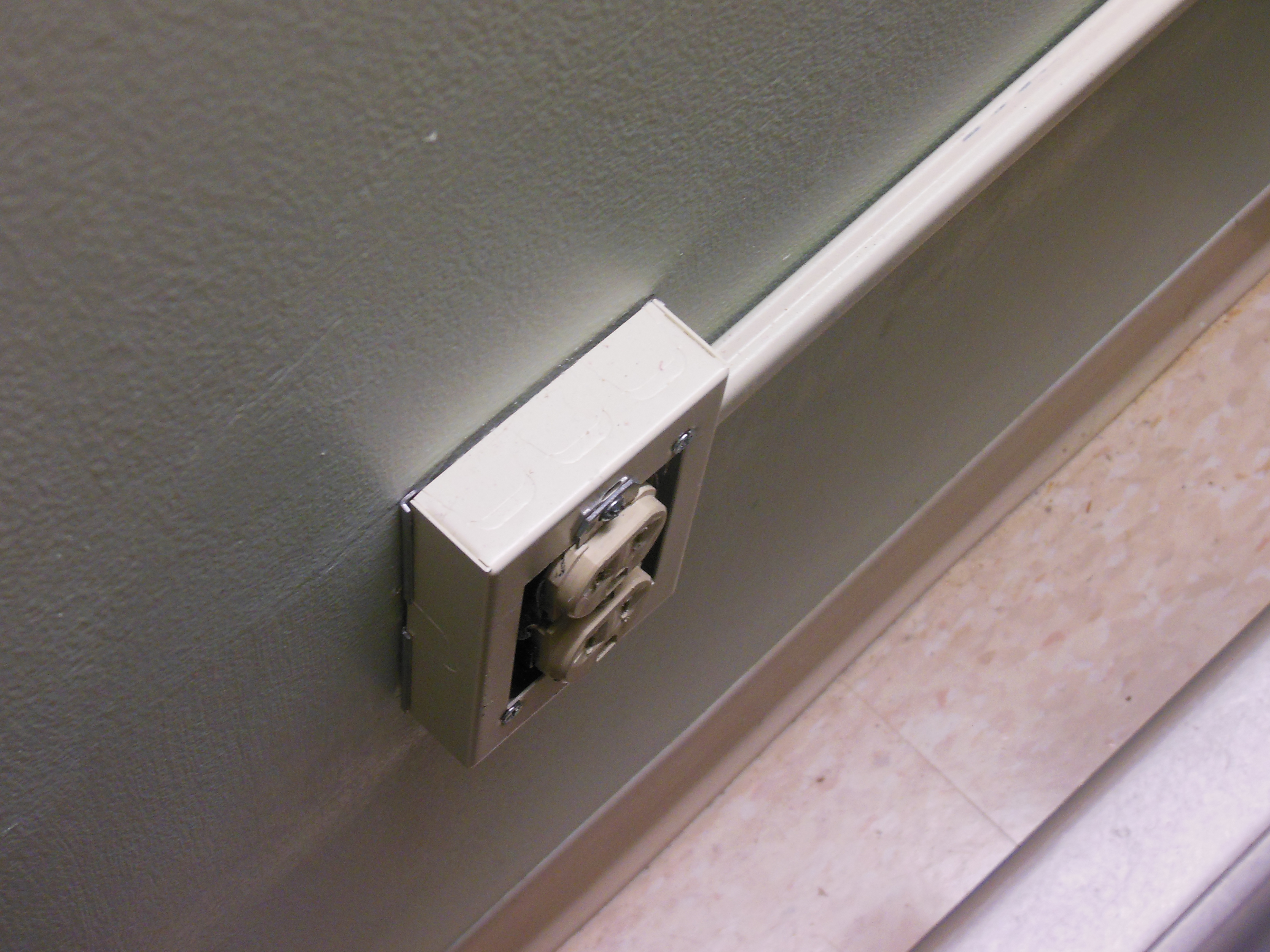
Location of power outlets and nurse call jack

Locations of bed and/or chairs

Place adhesive velcro strips in desired locations to more sturdily hold down your project box or button.

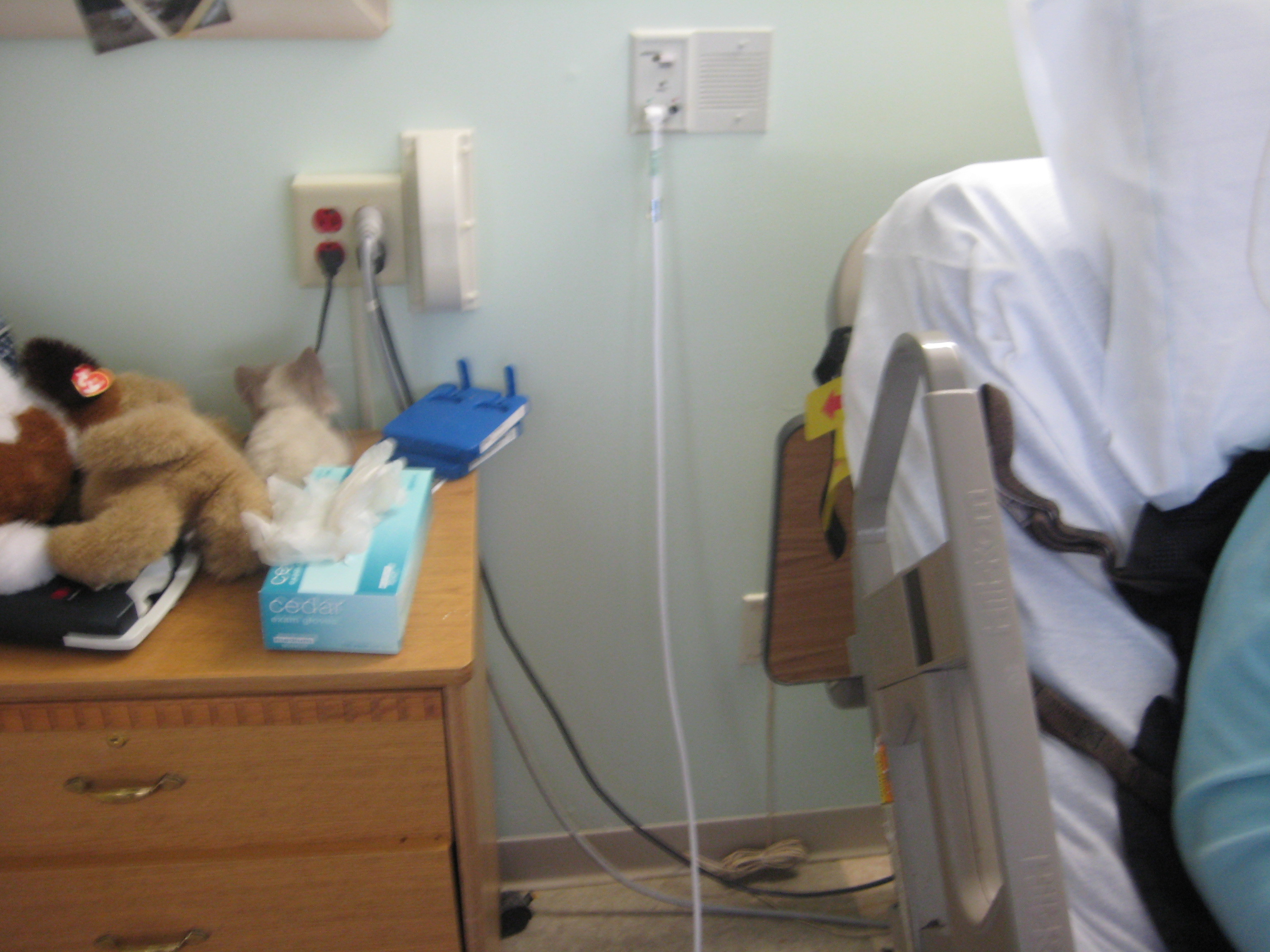
Put the first project box (button/LED combo) on the side table by the bed with the cord running underneath the bed to a Y-adapter.

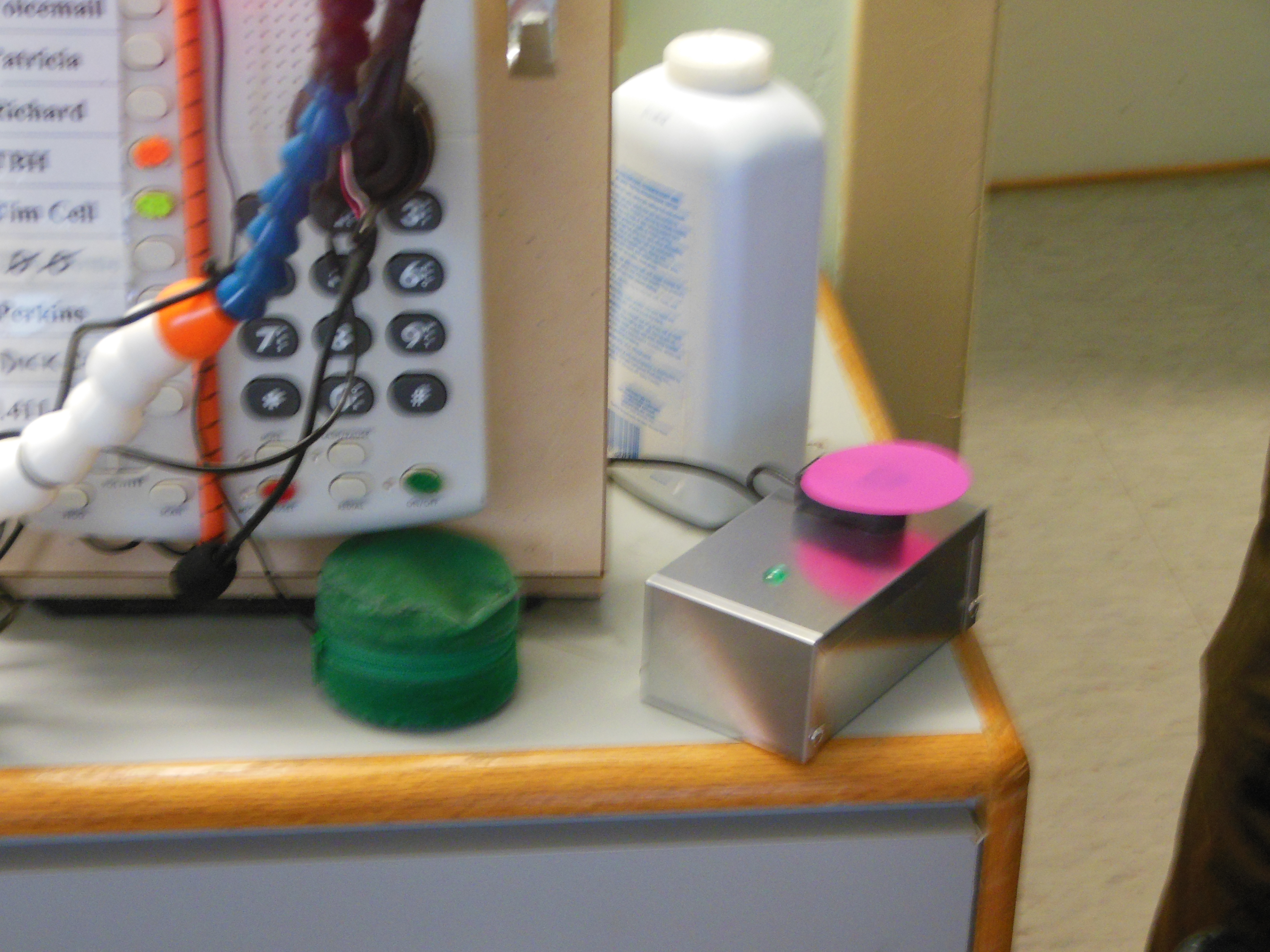
Put the second project box (microphone/LED combo) on the over-bed table with the second button velcro-attachable to the table or project box.

Run the respective cables to their proper destinations (power outlet, nurse call jack, Y-adapter).