YouTube player

This project uses the Seeed Studio GPRS/GSM Shield to build a versatile Arduino-based remote alarm system that can notify your cell phone within seconds, via text message, when nearby doors or windows are opened or closed, pressure sensors depressed, or motion sensors activated, just to name a few of the many possibilities.

gprs_system_diagram

Here we’ll teach you how to connect simple motion, touch, pressure, and light sensors, and how to program the Arduino to use the shield to send text messages when these detect events. It’s easy to adapt this system to use other sensor devices like temperature probes, magnetic switches, tilt sensors, etc. (If you’re looking for inspiration, check out Forrest Mim’s classic book Electronic Sensor Circuits and Projects.)

wp15_css_mainbuild

GPR…what was that again?

Back when cellphone technology was only “2G,” an industry standard data protocol was developed so that all phones, towers, and other cellular devices could talk to each other, even if they weren’t all made by the same company, regardless of what country they happened to be operating in.

That protocol survives today, and is known as GSM. The original French acronym—Groupe Special Mobile—has been superseded by an English one: Global System for Mobile Communications. Though 2G has been overtaken in many parts of the world by 3G and 4G technologies, even these more modern devices are required to be backwards-compatible with GSM.  As such, GSM remains the world’s dominant mobile phone data standard. GSM specifies a number of services that devices must provide in order to claim compliance. Among these is GPRS, or General Packet Radio Service, which is commonly used to provide text messaging, multimedia messaging, and internet access.
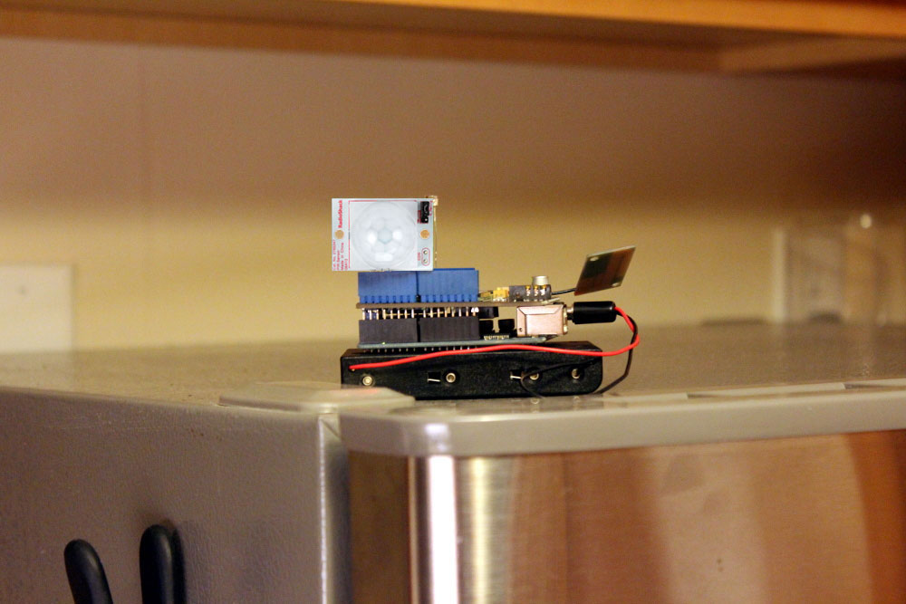
Power

You can power the Sensor Sentinel over your USB cable, through a wall-wart, or using a battery pack. During testing, it’s convenient to use the USB cable, but for true wireless use, you’ll want a battery. The method we’re using for capacitive touch sensing works poorly when powered through batteries, but relatively well when powered by USB or AC adapter.

Code

The Arduino code and a repackaged version of Paul Badger’s Capacitive Sensing Library are available for download from the MAKE Github repository.

Project Steps

Build the contact sensor

Cut a small rectangle out of cardboard, and transfer its shape to a piece of aluminum foil by tracing around it with a pencil. Cut out the aluminum foil rectangle, cut it in half, and trim all the edges of both halves about 1/8″. Glue the foil sections to the cardboard as shown. You want a narrow gap between the two foil sections and around all the edges.

Crease the cardboard in the middle, folding the foil-covered surfaces toward each other. Cut two sections of drinking straw about 1″ longer than the sensor is wide, on each side, and attach them across the foil on one side of the sensor by folding them around the back and securing the two ends with Scotch tape. You can change the amount of air trapped in each straw to adjust its springiness, which in turn will allow you to tune the sensitivity of the sensor.

Attach alligator clips to two opposing corners of the foil/cardboard rectangle and cut out the adjacent corners, with scissors, so that the clips will not short across the gap when the sensor is folded over.

Close the sensor and check its operation with the continuity tester on your multimeter. The straws hold the surfaces apart, but when something presses down on the middle, the two foil surfaces will connect, closing the circuit.

Build the capacitive touch sensor

While the contact sensor is basically an improvised momentary switch, the capacitive touch sensor is a little more sophisticated. it works by detecting the change in capacitance—the ability to hold electrical charge—of a metal sensor element when it comes in contact with another object.

NOTE: This sensor probably won’t work well on battery power, so if you know you’re going to be running on batteries, skip this sensor and try another.

To build the sensor itself, cut a rectangle out of cardboard about 5″ × 10″. Cover one side with aluminum foil, and glue the aluminum foil to the cardboard. Attach an alligator clip and wire to the foil.

Build the battery pack

Unscrew the connector sleeve from the power plug and slip it over the battery pack wires.

Double check that you have put the connector sleeve over the battery pack wires so you can slide it back up and screw it on over the connector when you are finished.

Triple check that you’ve put the connector sleeve over the wires before soldering.

The connector’s center pin is positive. Solder it to the red wire. The outside shell is negative. Solder it to the black wire.

If you forgot to put the connector sleeve over the wires, desolder the wires from the connector and do so now.

Gently crimp the connector terminal ears down to grab the wire insulation. This will provide strain relief on the solder joints. Don’t crimp too hard, or you may cut through the wire insulation and short out the connector.

Use your multimeter’s continuity tester between the sleeve and center pin of the plug connector. The circuit should test open (i.e. there should be no beep); if your meter beeps, there is a short. Fix it before proceeding.

Once you’ve fixed any shorted connections, pull the sleeve up along the wires and thread it onto the connector body. Put 6 AA batteries in the battery box.

Program the Arduino

If you haven’t already, visit arduino.cc to download and install the free Arduino software for your computer.

Download the Sensor Sentinel sketch and Capacitive Sensing Library from the MAKE Github repository. Put the sketch in your sketchbook directory, in a subdirectory called SensorSentinel. Follow the instructions at arduino.cc to install the library directly from the ZIP file.

NOTE: The Sensor Sentinel software has a variety of options you can set by making changes at the top of the program code. Texting is disabled by default, so you can get the sensor working as you like before enabling a service that may cost you money to use. With texting disabled, the Sensor Sentinel will only report events through the Arduino software’s “Serial Monitor” window. Before you enable texting, you’ll also need to replace the default phone number with the number of the phone you want to receive texts when the Sensor Sentinel is activated.

Connect the Arduino to your PC using the USB A-B cable. Under Tools, set the board to Arduino Uno (or whatever is appropriate for your Arduino board). Select the proper port. Press the upload button to send the code to the Arduino.

Open the Serial Monitor and set the baudrate to 115200. You should see “Hello World” appear in the Serial Monitor window.

Disconnect the Arduino from the computer.

Configure the GPRS 2.0 shield

NOTE: Your shield may come with the headers loose from the board; if so you’ll need to solder them in place so it can plug into an Arduino. A handy trick for getting everything aligned quickly is to first solder only one pin from each header to the shield. Once all the headers are “tacked” to the board, confirm everything is aligned by connecting it to an Arduino. If you need to adjust something, there’s only one pin you have to reheat and gently move. Once everything fits, solder all the pins.

Activate your SIM card using the package instructions, then load it in the GPRS shield’s connector, making sure the contacts connect. If you have a microSIM, use an adapter.

The small connector on the shield that connects to the external PCB antenna is called a Hirose U.FL connector. Connect the small wire from the PCB antenna to it now.

The two jumpers that select the serial port can either be set to HWserial or SWserial. We want to use software serial, so set them both to SWserial.

Make sure the Arduino isn’t powered, and then connect the GPRS shield to it.

Connect the Arduino to your PC using the USB A-B connector, and watch the serial output using the Serial Monitor at 115200 baud. You should see the green PWR LED light up on the board. The program will try to turn on the module, so wait a few seconds and watch for the Serial Monitor to print “Ready”, and you should see the red “Sta” LED light up on the shield. The “Net” LED might also blink green.

Just to demonstrate the power button, let’s press and hold the PWRKEY for two seconds. The lights should change as the cellular module turns off. Whether the module is on or off, when the program starts, the program will turn on the module.

Disconnect the Arduino from the computer.

Connect the sensors

Plug the PIR motion sensor into the board so that OUT connects to pin 2, VCC connects to pin 3, and GND connects to pin 4. Remember, Arduino pin numbering starts at 0. The GPRS shield doesn’t have pin labels, so reference the corresponding labels on the Arduino to double-check.

The light sensor has a long and short leg. Connect the short leg to GND and the long leg to A0.

Connect one of the contact switch alligator clips to the ground leg of the light sensor, and another to pin 10. If you have a jumper wire, you can use that to connect the alligator clip to pin 10. If you don’t, you can use the leg of an extra resistor. If it’s confusing, cut the leg off the extra resistor and use it as a little wire.

Connect the 10M resistor between pins 11 and 12. Connect the alligator clip lead from the capacitive sensor to the resistor on the part that plugs into pin 12.

Test and configure

Connect the Arduino to the PC using the USB A-B cable.

NOTE: Because this project sends text messages, and text messages can cost you money, there are some features in the code that help stop you from sending a thousand texts in a minute if there’s an issue with the sensors. By default, this project has the text messages turned off, but it will print to the Serial Monitor when it would have sent a text.

Open the Arduino Serial Monitor with the baudrate set to 115200. You should be able to see a “Hello world” message shortly followed by the shield radio turning on.

Before enabling outgoing texts, test each subsystem—put your hand in front of the PIR sensor, and verify that the serial monitor reports the correct event. The PIR sensor also glows red when activated. Press and release the contact sensor. You should see a press event and a release event on the Serial Monitor

The capacitive touch sensor needs a little configuration. First, it won’t work well when on batteries, so if you know you’re going to be on batteries, ignore the capacitive touch sensor tuning, and set CAP_SENSOR_ENABLED to false. There are two numbers, a lower and upper threshold. When the reading is above the upper threshold, it will trigger activation. When the reading drops below the lower threshold, it will trigger deactivation. The raw sensor value will print to the screen a few times a second. Watch the numbers as you put your hand closer and further away from the sensor, and choose appropriate settings. After changing these, you’ll have to re-upload the program to the Arduino.

Test the cellular functionality. Confirm that SMS_NUMBER has been set to a valid outgoing number. Confirm that MIN_MS_BETWEEN_SMS, which sets the minimum delay between text messages in milliseconds, is set relatively high—we recommend 30000 milliseconds (30 seconds) to start. Confirm SMS_ENABLED and SEND_SMS_AT_STARTUP is true. If you’re not using the capacitive touch sensor, set CAP_SENSOR_ENABLED to false.

After changing any values, be sure to reupload the modified code to the Arduino by pressing the upload button. Open the Serial Monitor—the shield should send a text message. Watch the Serial Monitor for errors. There shouldn’t be any. After 30 seconds or so, turn off the Arduino by unplugging it, and wait for the SMS to come through on the outgoing number. It shouldn’t take too long, though delivery time will vary with network congestion. The text messages will contain the trigger reason, the state of all the sensors, as well as the time the text was sent.

Deploy the Sensor Sentinel

Once the test message arrives successfully, you’re ready to deploy! You can use the battery pack, a wall-wart, or the USB cable to power the Sensor Sentinel. A rubber band is handy for connecting the battery pack to the shield and Arduino.

I tested the Sensor Sentinel on top of the fridge (with the PIR watching for people walking in front of it), in a book case (with the contact sensor positioned to notify me if anyone touched a particular book), and underneath my favorite chair (with the capacitive sensor tuned to detect someone sitting down in it).

Conclusion

You can change the sensors to detect just about anything, be it humidity, barometric pressure, magnetic fields, acceleration, vibration, flexing, tilt, etc. Initialize the sensor in setup(). If you want the sensor to trigger a message, check for the triggering condition in loop(), otherwise just read the sensor in annotateMessage(), put some text in the message variable and you're good to go!

There are Arduino libraries for interfacing with the module on the Seeed Studio GPRS Shield. They make it easier to do more complex stuff, but we chose not to use them in order to keep this sketch simple.

Going Further

The code for interfacing with the cellular module is based upon examples from Seeed Studio. It has a lot of delays. It would be possible to write a function to watch for "OK: in the cellular module's output. This would likely reduce those delays a bit, and make the code a little more robust.

Hook up a microphone to the MIC jack on the shield, and have the shield call you for 1 minute and then hang up. You could listen in remotely!

Have the cellular module check for incoming texts, and if you text it from your trusted number, have it reply back with sensor readings (or call you back so you can listen in!) Once you have this, you could attach servos, buzzers, anything, and trigger them from anywhere you have a cell signal!

Depending upon where you live, you may be able to text the Twitter shortcode and post to Twitter using this system.

Set up your Sensor Sentinel for low power draw! Normal Arduinos aren't really meant for low power/long battery life, so we didn't make power optimizations in this sketch. However, you could rig this up to "sleep" most of the time, and last a good amount of time on a battery, especially if you're only sending outgoing texts. You could even turn off the cellular module and program the Arduino to only turn it on when you need to send a text.