The Scientific Revolution was a momentous time. Most historians of science agree that during this era — 1500 to 1700 CE — people started thinking differently, more scientifically, about the way the world worked. Many began to think of the world as being an orderly machine, one in which laws and rules controlled the way nature worked. Although scientists, or natural philosophers as they were then called, did not necessarily know exactly what these laws were, they were certain they were there, working behind the scenes.

Subscribe to Make: for this and more projects and articles.

The superstars of the Scientific Revolution were Galileo, Copernicus, and Newton, but there were a number of other important thinkers as well: Robert Boyle, Johannes Kepler, and Rene Descartes, to name but a few. Often overlooked in the crowd of luminaries is the great Dutch scientist Christiaan Huygens. Huygens first made sense of Saturn’s rings; discovered Titan, the largest moon in the solar system; laid the groundwork for the physics of Isaac Newton; and designed and built one of the first vacuum pumps (see my article “Robert Boyle and the Air Pump” in Make: Volume 78.) But arguably, his most significant and practical invention was the pendulum clock.

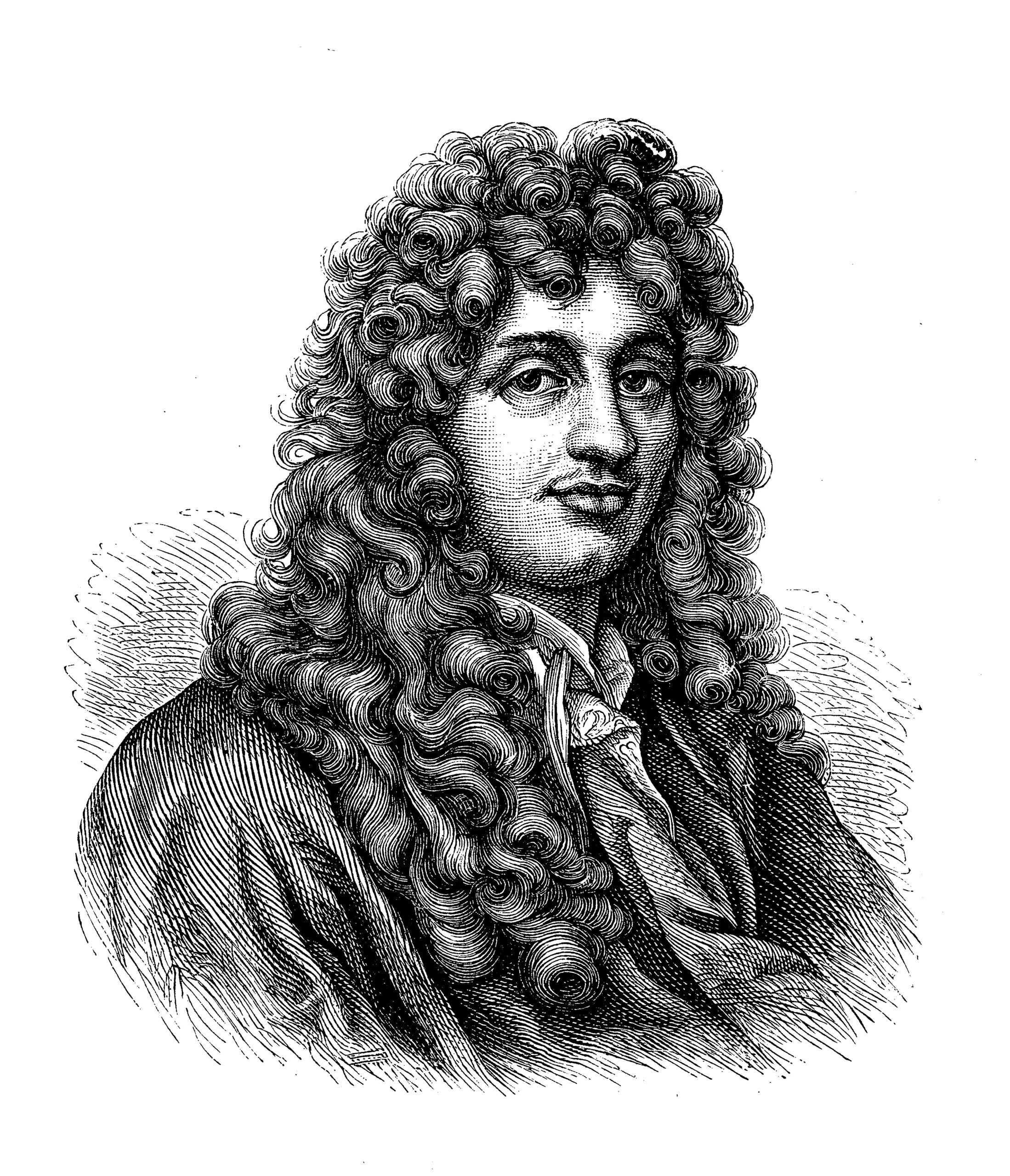
At the time Huygens lived, from 1629 to 1695, clocks were becoming increasingly important in daily life, but they were very inaccurate. The best of them could do no better than gain or lose more than 15 minutes in time every day. While a clock like that could tell you when it was time to eat lunch, it was not suitable for navigation or astronomical observations.

Inspired by Galileo Galilei’s investigations of pendulums about 75 years earlier, Huygens began thinking about how he could use pendulums to keep better time. Huygens knew that Galileo had found that pendulums had a fascinating property: they were isochronous, meaning that the time it takes for any single pendulum to swing back and forth is the same no matter how high the point at which the swing begins. This made them useful for keeping time because for a given pendulum length, the time interval for the swing back and forth is always the same. When Huygens substituted the constant-swing-rate pendulum for the imprecise balance wheel used up to that point, the error rate of a Huygens pendulum clock shrank from 15 minutes a day to 15 seconds a day! This was indeed a scientific revolution in timekeeping.

Portrait of Christiaan Huygens (1629 – 1695) Dutch physicist, mathematician, astronomer and inventor

In this edition of Remaking History, we recreate a Huygens-style pendulum clock escapement. An escapement is the heart of any non-electronic clock. It’s the mechanism that goes “tick-tock” and actually keeps time. Because Huygens’ original clock requires accurately cut gears which are difficult to make, we will instead build a simpler descendant called a single-pin escapement clock. The single-pin escapement isn’t widely used by clockmakers, but it certainly keeps time, is easy to build, and makes a loud and satisfying tick-tock when you get it to work.

Project Steps

1.

Build the frame for your escapement by joining the 2×4 and 2×2 boards as shown in Figure A, using 3 deck screws through the bottom.

A

2.

Use the jigsaw to make a 2½”×2½” square cutout centered in the 3½”×3½”×¾” escapement block. Next, drill 3/8″ holes into the center of the top and bottom of the ¾”-thick escapement block. Glue the 1¾” squares to the escapement block as shown.

When the glue is dry, slightly enlarge the opening where the two 1¾” squares meet, by cutting about ¼” off each corner (Figure B).

B

3.

Cut the crutch as shown in Figure C, then, drill the 3/8″ hole and 5/16″ hole as shown.

C

4.

Drill a 5/16″ hole in the center of the 2″×2″×¼” plywood square. Then drill a single 13/64 hole, 1″ away from the center hole in any direction. This piece is the crank.

5.

Drill two 11/32″ holes through the 2×4 frame piece as shown in Figure A. Countersink both ends of each hole 5/16″ inches deep with the 22mm (or 7/8″) Forstner bit. The top hole is for the pendulum shaft bolt and the bottom is for the crank shaft bolt. Insert a skateboard bearing in each hole.

6.

Insert the 5/16″ crank shaft bolt all the way into the center hole in the 2″×2″×¼” crank, so that it’s flush against the underside of the bolt head. Glue into place.

Insert the #10 bolt through the 13/64″ hole as shown in Figure D, and glue it in place too. This is the escapement drive pin.

D

7.

Use the C-clamp to attach the frame to a workbench. Insert the pendulum shaft bolt through the upper hole in the frame (Figure E).

E

8.

Similarly, insert the crank shaft bolt through the lower hole in the frame.

9.

Push the 5/16″ hole on the crutch onto the pendulum shaft bolt. Insert one end of the upper pendulum into the 3/8″ hole in the crutch, and the opposite end into the hole on the top of the escapement block. Slide the escapement up or down on the upper pendulum until the opening in the center of the escapement aligns with the axis of the horizontal crank shaft bolt, then cut the pendulum to length.

F

Insert the lower pendulum into the bottom hole on the escapement block. Use washers as spacers to align the crank bolt so the midpoint of the drive pin pushes against the escapement wings when the crank turns. The idea is that when the falling weight turns the crank shaft, the drive pin alternately engages the wings, which in turn pushes the pendulum back and forth. See Figures F and G.

G

10.

When you’re satisfied with the alignment, fix all the wood-on-wood connections with glue to prevent the parts from spinning. The completed single pin escapement is shown in Figure H.

H

11.

Wrap the protruding crank bolt with some tape to make a little drum. Then wrap a few feet of twine around the drum and attach 8 ounces of weight to the free end.

TICK TOCK!

Gently release the weight, and the crank will spin around within the escapement at regular, even intervals. Your clock is now ticking! If not, check the alignment or add more weight. Visit the project page  to see a video of how the single pin escapement looks when it’s ticking.

You can experiment by adding gears and hands and a clock face. If you want to make it tick slower, add weight to the bottom of the pendulum.