If you’ve ever struggled to use a solderless breadboard with an Arduino, you understand how frustrating it can be! The Boarduino clone acts just like an Arduino, and works with the latest Arduino software. For many projects it can even be preferable!
Projects from Make: Magazine
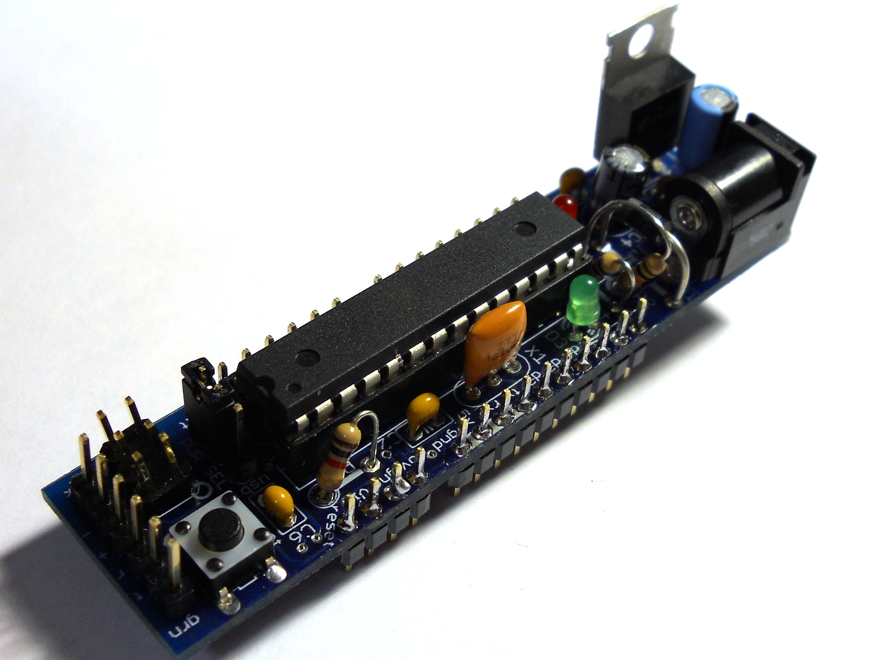
DC Boarduino (Arduino Clone) Kit
The DC Boarduino was designed to help you easily build breadboard circuits based on the Arduino platform.