YouTube player

Snowfall is often just measured by its depth in inches (or centimeters). But there are other important factors to consider. The density, the temperature, and the crystal shape all greatly affect how the snow behaves when you try to work with it. So it might be useful if we also measured other properties of snow as well.

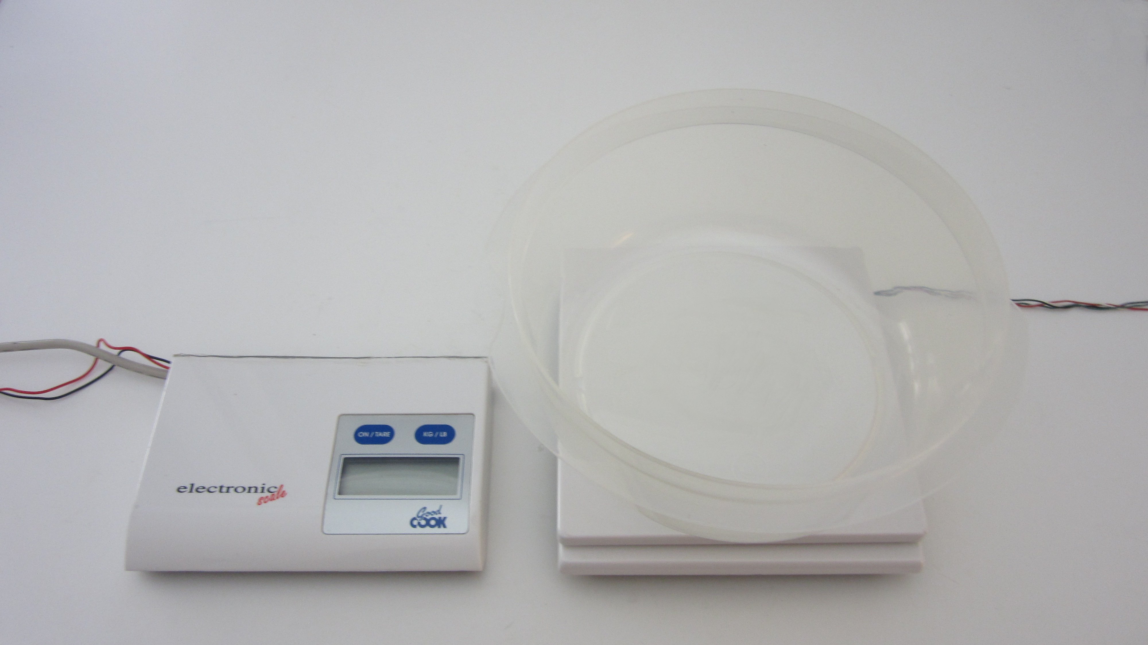
For instance, if you have to shovel snow, the thing that you are most concerned about is the weight of the snow. To measure this, I made a simple scale that can be read remotely. This lets you monitor the snowfall from the comfort of your warm house. It makes a great addition to any DIY home weather station.

Project Steps

Materials and Tools

Materials:

Kitchen Scale (preferably one that doesn’t zero itself when turned on)

Four Long Wires

Small Plastic Bowl

Scrap Plastic

Tools:

Fine Toothed Saw or Rotary Cutting Tool

Hot Glue Gun

Drill

Knife

Screw Driver

Ruler

Sharpie

Background: How a Digital Scale Works

Inside a digital scale you will find two main parts. There is a load cell that senses the weight of the object that is being measured and there are the various circuits that process the data from the load cell.

A load cell is typically a metal bar with a sensor glued to the side of it. On older scales this sensor would be a simple strain gauge that changes its resistance as the bar is deformed. The circuit measures the change in resistance and converts that to a weight measurement. Newer scales often have multiple sensors with built-in circuitry. These sensors output serial data that is then processed by the external circuit.

Most digital scales have a tare button that resets the reading to zero. This is very useful for calibrating the scale. However, some scales automatically reset themselves every time that they turn on. This feature is very problematic for this design. This would require the scale to be constantly on in order to measure any new snowfall. If you have this kind of scale, I would recommend using an Arduino to monitor the output of the load cell instead of using the original monitoring circuit. This option is discussed more in step 11.

Open the Housing of the Scale to See How All the Parts Are Laid Out

The first thing that you need to do is open up the housing of the scale to see where the parts are located and how they are connected to each other. The plate will typically twist off. After removing the plate, you should be able to unscrew the rest of the parts. Keep in mind that screws are sometimes hidden behind stickers or the rubber pads on the bottom.

On this scale the load cell takes up half the housing and the monitoring circuit takes up the other half. The load cell is connected circuit board with a single 4-wire cable. The load cell and the circuit board are both attached to the housing with screws.

Remove All the Parts From the Housing

In order to be able to monitor the scale remotely we need to separate the load cell and the monitoring circuit. To do this, first unscrew the load cell and the circuit board from the housing. Then disconnect the load cell cable from the connector pins on the circuit board.

Cut the Housing into Two Sections

You now have several options as to how to mount the load cell and the circuit board. You can create a new housing for either the load cell, or the circuit board or both. Another option is to just cut the current housing in half and then mount each part back in its original location. This is the easiest option because the two parts were separated by a reasonable gap in the housing. So a single straight cut would separate the two sections.

Once all the internal parts had been removed, I fit the two pieces of the housing back together and I marked a line between each section. Then I used a fine toothed saw to slowly cut through the whole housing.

Connect the Load Cell to the Circuit Board With Extension Wires

We need a way to connect the wires from the load cell to the pins on the circuit board. The ideal way is do this is to use the same type of connectors that are used on the load cell cable. This is a standard four pin header cable. If possible match up the colors of each cable to help avoid confusion. If you don’t have this type of connector, then just solder the wires directly to the pins and cover them up with heat shrink tubing.

monitoring circuit. I wanted to set up the monitoring circuit in my kitchen window and the sensor a few feet out in the yard. So I used about ten feet of wire to connect the two parts.

Mount the Scale Parts Back into Each Section

Mount all the parts back in their original locations on the housing. Once everything is in place, turn on the scale and test it to make sure that it is working properly. If not, check to make sure that all the wires are connected to the correct pins.

Seal the Cut Opening on Each Section

After cutting the housing, each section is open on one side. To prevent anything from getting inside, I sealed the opening with a small piece of scrap plastic. I traced the outline of the opening onto a sheet of clear plastic. Then I cut out the plastic and attached it to the opening with hot glue. This does not make a perfect seal. If you want it to be weather proof, then you should sealants that are designed for exterior weather proofing.

Mount a Bowl to the Plate to Catch the Snow

A flat plate can miss snow that is blown at an angle. To account for this, you can add a small bowl to the plate. The sides of the board will help to catch and hold the snow so that it does not blow off of the plate. I found a small plastic bowl that fit on the plate. I drilled a few small holes in the bottom to allow melted snow to drain out. Then I mounted the bowl to the plate with hot glue.

Set Up the Scale to Monitor Snowfall

Now all you need to do is position the sensor outside and wait for it to snow. I mounted the digital readout on the inside of my kitchen window and I placed the sensor a few feet out into the yard. You can either place the scale on the ground or you can hang it from a plant hanger. Make sure that it is out in the open where it will receive direct snowfall.

Alternative Setup: Monitor the Snowfall With an Arduino

If you do not wish to use the original monitoring circuit, you also have the option of using an Arduino instead. If the load cell of your scale uses a simple strain gauge, you can wire it in series with a fixed resistor and use the Arduino’s AnalogRead function to measure the voltage of the center pin. If your load cell outputs series data, that can be read directly with the serial read function. Using an Arduino gives you quite a few options as to how you will monitor and process your snowfall data.