YouTube player

Many people find the beep of an alarm clock to be a very unpleasant way to wake up. One alternative is to use lights to wake you up. For instance, a “sunrise alarm clock” gradually increases the brightness of a light near your bed at the set time. This helps some people to wake up more gently.

In this project, I am going to show you how to make a simple light alarm circuit. The timing is performed by a cheap outlet timer. Then I add a simple LED circuit that gradually increases the brightness of the LEDs over several minutes. You can then put the lights into any housing that you want and make your own sunrise alarm.

Project Steps

Materials

Here are the materials that you will need to make the circuit:

AC Outlet Timer,

USB Cable,

USB AC Adapter,

IRF510 MOSFET,

1 Mohm Resistor,

4 X 100 ohm Resistor,

10 kohm Potentiometer (Variable Resistor),

1000 µF Capacitor,

4 X LED,

Printed Circuit Board,

Jumper Wires,

Extension Wire (optional),

Momentary Switch (optional)

The Circuit

This circuit is essentially just a resistor/capacitor timer with a transistor amplifier. The capacitor is initially discharged. When the power is turned on, the capacitor begins to charge through the 1Mohm resistor. As this is happening, the output voltage of the capacitor slowly increases. This voltage signal is sent to the transistor which sets the transistor’s output. This causes the LEDs to gradually increase in brightness over several minutes.

The potentiometer (variable resistor) is used to adjust the starting voltage of the capacitor. This effectively lets you set the initial brightness of the LEDs. Without it, the LEDs would be off for a long period of charging before the output would be high enough for LEDs to begin to emit light.

The values of the 1000 µF capacitor and the 1 Mohm resistor were arbitrarily chosen for convenience. Increasing either of these values will slow down the charging process and cause the LEDs to brighten more slowly. Decreasing either of these values will have the opposite effect.

The IRF510 MOSFET was chosen for the transistor because it requires very little input current and is capable of driving a large number of LEDs.

Optionally, you can connect a normally open momentary switch to the two terminals of the capacitor to act as a snooze button. Pressing the button will drain the capacitor and restart the charging cycle.

Assemble the Circuit

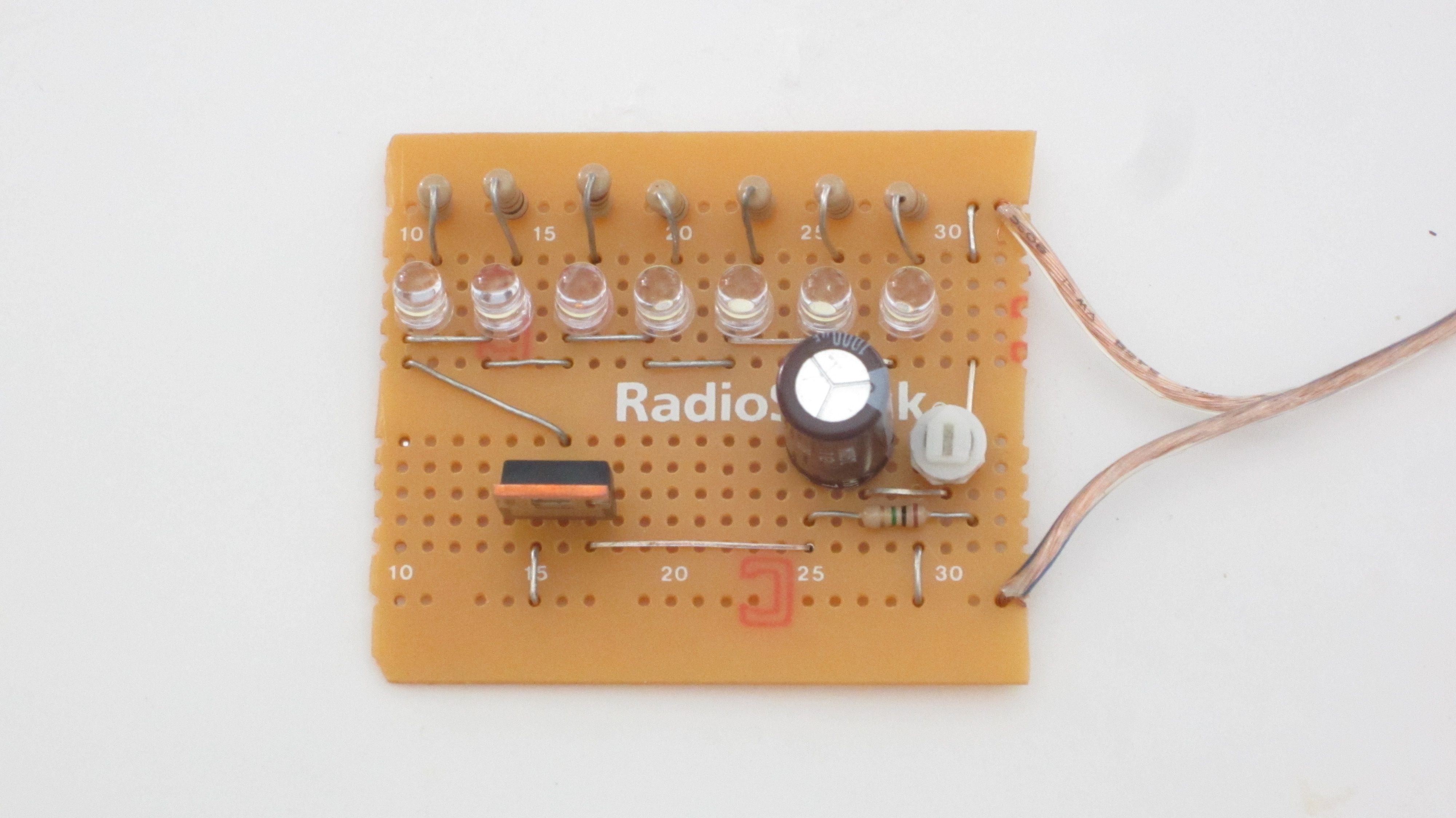
Following the circuit diagram in the previous step, I prototyped the circuit on a breadboard. After testing the circuit to make sure that everything was functioning properly, I soldered the circuit together on a printed circuit board. I decided to add a few more LEDs to make it a little brighter. Then I trimmed the circuit board to fit. Depending on how you plan to mount the lights, you may wish to add additional wire so that you can reach areas that are further away from the outlet.

Mount the Circuit

There are a lot of ways that you could mount the light. The simplest way is to just place it next to your bed on your night stand. This can work but it is less effective if you are facing the other direction. Another option is to mount it over your bed in something like a hanging lantern. If you want the light to be more directional, you can mount it in an adjustable lamp that can be pointed at your pillow. If all else fails you can put the lights directly into a pillow, such as “Bright Light Pillows.” Do whatever works best to wake you up.

Set Up the Timer

Plug the timer into the wall outlet. Plug the USB AC adapter into the timer. Then plug the USB cable into the adapter. Set the timer to turn on about 15 minutes before you want to wake up. When the timer goes off, it will activate the circuit. The LEDs will then gradually turn on and hopefully wake you up.

Finished Sunrise Alarm Clock

Now you have your own DIY sunrise alarm clock. When you are first trying it out, you may wish to have a regular alarm as a backup just in case the light doesn’t wake you up reliably.