Don’t miss author Brandon Satrom building this project live on air! Watch Make: Live on Friday March 22, 5pm ET/2pm PT on Youtube or Facebook.

YouTube player

Hacking a toy is a fun way to see how real-world electronics are designed and built, and to tinker freely without ruining expensive gear. And cheap consumer electronics generally are a fantastic platform for learning and even building new, innovative solutions. So when Make: asked me for a DIY swarmbots project, I knew just where to go.

Radio-controlled (R/C) vehicles are a common target for makers, and cars with the Thunder Tumbler name provide an affordable, accessible platform for R/C car hacking. The Tumbler has been hacked a number of times before, but I don’t think it’s ever been used in a mesh network. That is, until now. Using Particle’s new, mesh-ready hardware, I created a swarmbot network of Tumblers that move in synchronized fashion at my every command!

A Lesson About Meshin’

How does mesh networking work? Most connected solutions rely on Wi-Fi or cellular networks for connectivity. This typically means that each device maintains its own connection to the internet. While this is useful for accessing the cloud for data storage or processing, sometimes you just want your gizmos to connect with other devices locally, regardless of whether an internet connection exists.

Mesh networking enables these scenarios by allowing you to create local networks of connected devices. The bulk of the network consists of endpoints that sense or actuate, and repeaters that increase the size and reliability of the mesh by passing messages between devices. In addition, a small number of devices — often just one — serve as gateways to maintain a connection to the internet. Critically, these local networks of devices can still communicate with each other when the internet connection disappears. For jobs like this, the Argon, Boron, and Xenon microcontrollers from Particle all provide built-in mesh-networking capabilities.

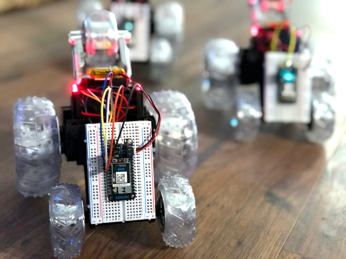
For this build, I used the Particle Mesh platform to create a network of R/C cars, each controlled by a Particle Xenon. All of the Xenon R/C cars are endpoints, and are connected to a mesh network with a single Particle Argon as the gateway. Once the network is established, I can use local network messaging to send low-latency commands to all nodes on the network and make my R/C cars dance.

First, however, I needed to hack the off-the-shelf Tumblers to Particle-power them!

Project Steps

1. HACK THE THUNDER TUMBLER

The first step is hacking the R/C car to add a Xenon. Whichever brand or style of R/C car you’re using, the objective is to crack open the car to reveal the PCB inside, determine how the device sends commands to the motors to rotate the wheels, and then connect pins from the Xenon to the corresponding motor driver pins on the car. Because these cars are inexpensive, you should expect to find some variation, even among those with the Thunder Tumbler name on the box.

Write-ups on Tumbler hacking can be found online going back over 9 years. That’s a lifetime in the electronics world, so be sure to test and verify the functionality of your cars as you follow these instructions. Grab your favorite multimeter and measure voltages across various pins on the R/C car’s PCB as you make the wheels spin with the remote control. Make sure to set your car somewhere where the wheels can rotate freely so that it doesn’t get away from you during testing.

Remove the two screws that hold the car body in place, then lift the shell to expose the PCB. You’ll see 8–10 wires that run from the car to the PCB, and a number of through-hole and surface-mount components.

The small surface-mount component on the top is a radio-control receiver chip, the RX-2B. Its pair, the TX-2B transceiver chip, sits in the remote control transmitter. These ICs are commonly used for R/C vehicles, and I was able to find their datasheets to determine which pins map to the forward, backward, left, and right commands from the remote. I also used the datasheet to establish a known ground pin; you’ll need this to determine which pins power the car motors and can be controlled by a Xenon.

This ended up being critical because the main IC on these boards, through-hole mounted on the bottom of the car PCB, is one for which I couldn’t find a datasheet, in spite of many hours of searching. While I’m still not 100% certain of all the features on this chip, it functions primarily as an H-bridge motor controller. Pulsing a signal into a certain pin on the IC results in a pulse out to one of the motor control pins, which makes a wheel spin forward or backward.

By reverse engineering, I found that there are four pins I care about on this unknown IC: one that spins the left wheel forward, one that spins it back; one that spins the right wheel forward, and one that spins it back. I soldered one wire to the top of each of these pins, and one to a ground pin (above). Even though the Xenon and car are powered separately, they need to share a ground for everything to work right.

Then I connected these wires to Xenon pins A1, A0, A2, A3, and GND, and powered up the Xenon with a LiPo battery (above).

2. SET UP A MESH NETWORK

Your mesh will have one gateway (a Particle Argon or Boron) and one Xenon-based node for each R/C car. If you want to program your Xenons over-the-air without having to connect each to a computer, you’ll want to set up your network in advance. You can do this from the Particle mobile app (below), or follow the instructions at particle.io/start.


3. PROGRAM THE TUMBLERS

Once you have your first Xenon claimed and ready, the next step is to write firmware to the Xenon for controlling the actions of each car. Since the goal here is to create a small mesh of swarmbots, you’ll start with a simple test sequence that moves the car forward, back, left, and right. The code for this sequence can be found below and at github.com/particle-iot/mesh-rc-cars. Upload it to your Xenon just as you would to an Arduino; if you need instructions they’re in a Readme at the GitHub repo.

// Wheel pin mappings
int leftReverse = A0;
int leftForward = A1;
int rightForward = A2;
int rightReverse = A3;

// Speed and delay variables
int speed = 85;
int turnSpeed = 255;
int forwardDelay = 1000;
int backDelay = 1000;
int turnDelay = 2000;

void setup()
{
 // Set motor pins to outputs
 pinMode(leftReverse, OUTPUT);
 pinMode(leftForward, OUTPUT);
 pinMode(rightForward, OUTPUT);
 pinMode(rightReverse, OUTPUT);

 // Make sure each motor is off
 digitalWrite(leftReverse, LOW);
 digitalWrite(leftForward, LOW);
 digitalWrite(rightForward, LOW);
 digitalWrite(rightReverse, LOW);
}

void runDemo(const char *event, const char *data)
{
 allOff();

 goForward(speed);
 delay(forwardDelay);

 goBack(speed);
 delay(backDelay);

 // Max spin to raise up on the back tires
 turnLeft(turnSpeed);
 delay(turnDelay);

 allOff();
}

void allOff()
{
 analogWrite(leftReverse, 0);
 analogWrite(leftForward, 0);
 analogWrite(rightForward, 0);
 analogWrite(rightReverse, 0);

 delay(50);
}

void goForward(int speed)
{
 allOff();

 analogWrite(rightForward, speed);
 analogWrite(leftForward, speed);
}

void goBack(int speed)
{
 allOff();

 analogWrite(rightReverse, speed);
 analogWrite(leftReverse, speed);
}

void turnLeft(int speed)
{
 allOff();

 analogWrite(rightForward,
speed);
}

void turnRight(int speed)
{
 allOff();

 analogWrite(leftForward, speed);
}

void loop()
{
 // Nothing needed here.
}

You probably noticed that the meat of this demo is analogWrite commands to turn each wheel forward or backward by sending a voltage to a corresponding pin. Through testing, I determined that the cars I’m using are PWM-able, meaning that I can set a wheel pin to lower voltages than digital HIGH (3.3 volts in the case of the Xenon) and have the wheel turn at lower speeds. Notice that I’m passing in different values for turning right or left versus forward and back. PWM (pulse-width modulation) enables pretty complex patterns and speeds for these inexpensive cars!

With the demo code done, the final piece you need on your R/C cars is a subscription to a local network message that specifies the runDemo function as the handler. Particle enables local, in-mesh-network messaging between nodes on a network using a Mesh.publish and Mesh.subscribe API. Mesh.publish sends a broadcast message (with a name and payload) to all nodes on the network. Mesh.subscribe, on the other hand, listens for messages (by name) and specifies a handler to process and respond to those incoming messages.

Our Xenons will use Mesh.subscribe to listen for a network message, and then trigger the demo sequence.

// Add to setup function
Mesh.subscribe(“run-demo”, runDemo);

Flash the completed code to each R/C car Xenon and you’re ready for the final piece: programming the gateway to coordinate the movements of the car swarm.

4. PROGRAM THE MESH GATEWAY

The gateway code that runs on the Argon is less complex than the code on the Xenons, but still needs two pieces: a Mesh.publish call to trigger the R/C car demo sequence, and a way to tell the Argon to fire that message out to the mesh network.

You could just fire the message when the gateway comes online, or regularly on a delay, but what fun would that be? Instead, you’ll use another Particle API, Particle.function, to trigger the cars from a mobile phone whenever you want.

void setup() {
  Particle.function(“runDemo”, runDemo);
}

int runDemo (String command)
{
  Mesh.publish(“run-demo”, NULL);

  return 1;
}

void loop() {
  // Nothing needed here
}

Particle.function takes a string value name of the function (used when calling that function from a mobile or web app or through the cloud) and a handler function to execute when called. That function contains our Mesh.publish call, which sends a broadcast message with the name “run-demo” to all listeners (i.e. our R/C cars) on the network. Once you’ve added the code on the previous page to your gateway, you’re ready to control some swarmbots (above).

5. PUT IT ALL TOGETHER

Particle functions can be called from any device that has a secure connection to the Particle Device Cloud, which could be the browser-based Particle Console at console.particle.io (below top), the Particle command-line interface or CLI (below middle), or your own applications. They can also be called from the Particle mobile app (below bottom), which seems like a fitting place to finish this project.

The mobile app shows a listing of every Particle device you own. Click on your gateway, then the Data tab menu, and you’ll see a “runDemo” function. Put your Xenons in position with plenty of space, and click the function to trigger some R/C swarming!

The demo code illustrates a simple, coordinated sequence of actions. But with PWM and some trial and error, you can create any number of cool synchronized dances with mesh-networked R/C cars.

Command Your Swarm!

Now that your bots are meshed, let’s turn them into real swarmbots that can communicate with each other. A common swarm scenario is the leader-follower pattern. The leader determines movements for the swarm, and communicates these directly to all followers. One example would be to control the leader with the out-of-box remote control, read pin voltages off the leader car, and send these as instructions to all followers listening for a Mesh event.

To build this demo, I designated one of my three cars as a leader, and added firmware to control the fleet. Instead of writing to my motor pins, the leader simply reads the analog values sent by the remote control and sends these to listeners on the network with a Mesh.publish that includes the wheel, direction, and analog value to apply to follower cars.

int32_t lastLeftRVal = 0;
int32_t lastLeftFVal = 0;
int32_t lastRightRVal = 0;
int32_t lastRightFVal = 0;

#define MIN_PIN_VAL 150
#define DRIVE_VAL 200

void setup()
{
  pinMode(leftReverse, INPUT);
  pinMode(leftForward, INPUT);
  pinMode(rightForward, INPUT);
  pinMode(rightReverse, INPUT);
}

void loop()
{
  checkPin(leftReverse, &lastLeftRVal, "leftR");
  checkPin(leftForward, &lastLeftFVal, "leftF");
  checkPin(rightReverse, &lastRightRVal, "rightR");
  checkPin(rightForward, &lastRightFVal, "rightF");
}

void checkPin(int pin, int32_t *lastVal, const char *event)
{
  int32_t pinVal = analogRead(pin) / 16;
  
  if (pinVal > MIN_PIN_VAL)
    pinVal = DRIVE_VAL;
  else
    pinVal = 0;

  if (pinVal != *lastVal && pinVal == DRIVE_VAL)
  {
    *lastVal = pinVal;

    Mesh.publish(event, String(DRIVE_VAL));
  } else if (pinVal == 0 && *lastVal != 0) {
    *lastVal = 0;
    
    Mesh.publish(event, String(0));
  }
}

On the follower side, I added firmware that listens for a Mesh event for each pin, and performs an analogWrite with the passed-in value. On the cars themselves, I also removed the antenna on each board and cut the traces from the remote’s RX IC just to make sure that movement commands were only coming from the leader.

void setup()
{
  pinMode(leftReverse, OUTPUT);
  pinMode(leftForward, OUTPUT);
  pinMode(rightForward, OUTPUT);
  pinMode(rightReverse, OUTPUT);

  digitalWrite(leftReverse, LOW);
  digitalWrite(leftForward, LOW);
  digitalWrite(rightForward, LOW);
  digitalWrite(rightReverse, LOW);

  Mesh.subscribe("leftR", leftR);
  Mesh.subscribe("leftF", leftF);
  Mesh.subscribe("rightR", rightR);
  Mesh.subscribe("rightF", rightF);
}

void leftR(const char *event, const char *data)
{
  move(leftReverse, data);
}

void leftF(const char *event, const char *data)
{
  move(leftForward, data);
}

void rightR(const char *event, const char *data)
{
  move(rightReverse, data);
}

void rightF(const char *event, const char *data)
{
  move(rightForward, data);
}

void move(int pin, const char *speed)
{
  int32_t speedVal = atoi(speed);

  if (speedVal > 16) // Filter out noise from the leader
  {
    analogWrite(pin, speedVal);
  }
  else
  {
    analogWrite(pin, 0);
  }
}

void loop() {}

With this simple R/C-controlled swarm as our foundation, we built a bunch more swarm sequences:

  • Follow the leader — basic forward and back demo with ending spin️
  • Splinter — cars separate in three different directions and come back together
  • Follow the leader and push — leader tells followers to stop, goes forward 2 seconds, turns around, goes back 2 seconds, then tells followers to move backward as it keeps moving forward
  • Sentry mode — square path with right-angle turns
  • Orbit — followers orbit a stationary leader.

You can grab the complete project source code, including these more complex demos, from the repository at github.com/particle-iot/mesh-rc-cars. I’ve also done a number of Twitch streams focused on building the demos for this project; check them out at twitch.tv/brandonsatrom.

Hack It and Share It

We’d love to see makers extend and modify this project with sensors and new behaviors. You could add collision detection to the leader with a PIR or ultrasonic sensor, or even use the remote to log predefined sequences that could then be repeated automatically. And if you’ve built your own mesh-style swarmbot project, or anything else with Particle’s new hardware, we’d love to hear from you! Share with us on Twitter (@Particle), Instagram (@Particle_iot) or in our community of 160,000 developers at community.particle.io.

Swarm on, makers!