


The basic idea of my low-cost thermal imager started with my physics class in 2010. Our teacher bought a single-point infrared thermometer, also called a pyrometer, and asked if anyone wanted to use it for a science competition later that year. A friend and I came up with the idea of creating a thermal image scanner using servomotors to move the infrared sensor over a large area.
Our first prototype was nothing more than a proof of concept; we used Lego Mindstorms together with a data interface for the sensor on the PC and an automated mouse/keyboard script for Adobe Photoshop to create low-resolution thermal images. I improved our design for the next year’s competition (Figure A), which I called the “Cheap-Thermocam V1.” It consisted of an Arduino microcontroller, two servomotors, and computer software written in Java; the total material cost was only about $100.

First Kits


In 2011, I won a special prize and published the software and hardware concepts to the internet. The feedback was positive — many people built their own adaptation of the device (Figure B), and others expressed interest in buying one. This led me to the second version of the device (Figure C) in mid-2013, which I sold online to people from all over the world. I was 20 at that time, so this was a huge step for me. The “Cheap-Thermocam V2” featured a small LCD display, which could be controlled over a rotary encoder and had the option to save data to an SD card.

A year later, I finished my work on the “Cheap-Thermocam V3 (Figure D),” which integrated a large touch screen, a slim design, and a much faster microcontroller. Versions one to three used the original principle of a movable single-point IR sensor that scans an area. While this had the advantage of being very cheap, it also took a couple of minutes to create one full thermal image. For many applications including moving objects, this approach was not suitable, so I was looking for an alternative.

A New Sensor

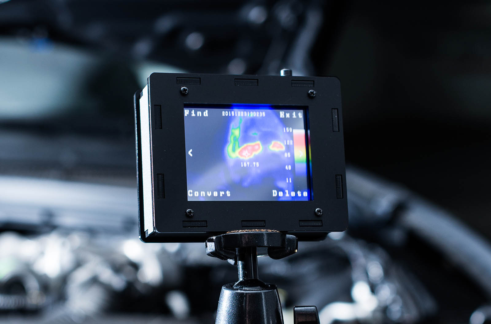
In 2014, FLIR released their Lepton sensor (Figure E), which was the first low-cost thermal array sensor on the market. I included it in the next version of my device, which I called the “DIY-Thermocam V1.” It was a big improvement from the scanning-principle to high-resolution, real-time thermal images and the starting point towards a serious alternative to the solutions on the market from big companies like FLIR or FLUKE.
Version 2 of the DIY-Thermocam provides many enhancements, including support for the Lepton 3.0 sensor with four times increased resolution, a more powerful microprocessor, a better and faster visual camera, and removable storage. A new video output module offers the option of streaming a video output signal of the data from the Thermocam.
A big advantage of the Thermocam is the open-source software and hardware, so you can modify it to your own needs or use it as a starting point for your own developments in the field of thermal imaging. The on-device firmware can be controlled with an easy-to-use touch menu and offers many features, like different color schemes, analysis, or saving methods. For analysis of the thermal images and videos on the PC, the raw files are fully compatible with a powerful application called ThermoVision, developed by a German programmer from Berlin. There’s also a Python application that offers real-time streaming of the thermal data on the computer and has some analysis features.
Lessons Learned
There were so many challenges along the way. In most cases I was able to solve them, in others I decided to try more unconventional solutions. For example when designing the case, I first wanted to use a 3D printer to produce it. However, it turned out that even the more expensive printers required a lot of post-printing refinement by hand. This took too long to be productive. Injection molding was not a real alternative either, as creating a mold was excessively expensive for making a small number of units. In the end, I decided to laser cut an enclosure, a relatively cheap technique that requires no post processing. I found a company in Germany who cut the parts for me out of black acrylic.
One thing I learned was not to set the time schedule for the release too tight, because, inevitably, many unexpected problems will occur. A good rule of thumb I found for myself is to make a schedule and then double it. If you’re done earlier, that often isn’t a problem, because you always find something to improve on.
I learned everything I needed for this project from sources on the internet and from books. There was almost nobody that helped me with it. This was a steep path, but I learned so much from it! The project required many steps: making the prototype, choosing the components and materials, making the device easy-to-assemble, quality checks, worldwide delivery, marketing, and customer contact, just to name a few. Many of the things I did were trial and error, and I really made plenty of mistakes during those years. However, all of them contributed to the treasure of experiences I have today, so it was worth making all of them. I would even say that I learned more working on the Thermocam project than from my five years of studies. In my opinion, you make the most progress — both personally and technically — when you actually work on challenges by yourself.

Build It!
If you get the kit, the assembly is pretty straightforward — about 2–4 hours depending on how fast you can solder. You can find all the steps, with images, on the GitHub page. Be sure to share your finished creation with us!


