At normal listening distances, an array of twelve speakers arranged on the faces of a dodecahedron is a very good approximation of a point sound source, and the sound waves it produces are very close to perfectly spherical. A dodecahedron speaker can be a useful tool in acoustics research, and is definitely a fun toy to pull out at parties. They are available commercially, but very expensive. Some people build their own, but the odd compound angles and the high degree of accuracy and precision required in the parts make for challenging work with manual tools. But it’s easy for a 3D printer.

If you have a RepRap, MakerBot, Up!, MakerGear, Ultimaker, or other suitable fused-filament printer, you can print and build this speaker for just under $100 in parts and materials. That includes speakers, hardware, wires, cable, plastic filament–everything.

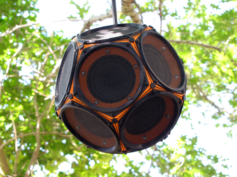
The high symmetry of the dodecahedron is amenable to a modular design, and this one consists of four basic parts: the face modules, the vertex plugs, the edge gaskets, and the bezels. The 3D models are all available on Thingiverse. The speaker grilles are made from hardware store window screen cloth installed in the bezels using rubber spline and a screen roller tool, just like a residential window screen.

The assembled speaker array weighs 5.6 lbs, not counting the cable, and measures 7.5″ across, from face to face, and 8.6″ from point to point. The speakers are wired in a hybrid series-parallel circuit that brings the total array impedance to about 10 ohms (again not counting the cable) which should be a comfortable load for most amplifiers.

Project Steps

Prep the cable

One end of your cable will connect to your amplifier or other audio source, and depending on that source, you may want to leave the 1/4″ phono plug as is, remove it, or replace it with some other type of connector. The other end of your cable connects to the speaker and will need to have the plug removed and the cable leads exposed.

The easiest way to remove the plug is to just cut it off a short distance behind the ferrule with a pair of sharp scissors. Toss it in your spares box and desolder the inch or so of attached cable when and if you use it, later.

Slit the rubber cable sheath with a hobby knife for an inch or so at the end. Try to cut between the wires, but don’t worry too much if you nick one.

Grab the two halves of the split sheath and “banana peel” it back three inches, or so, exposing as much of the wire pair as you need.

If you nicked the wires while cutting through the sheath, snip the ends off far enough back to remove the damaged part(s). Once you’ve got two inches of good wire pair exposed, trim away the excess sheath bits.

Tie a strain-relief knot in the cable another two inches back, or so. This knot, which is much too wide to pass through the narrow opening where the cable will exit the cabinet, will bear the weight of the hanging speaker.

Finally, strip about 3/4″ of the insulation from each of the wires, exposing the copper strands.

Print the plugs

This is the smallest of the three printed parts. It measures 10 × 10 × 9.6 mm and, if printed individually, takes about six minutes to extrude. In PLA, each one weighs about 370 mg and uses about 125 mm of 1.75 mm diameter filament. I printed mine in black.

You’ll need nineteen of them, one for each of a dodecahedron’s twenty vertices, less one vertex that’ll be occupied by the speaker cable. They are pushed into place after the cabinet is assembled, and are designed to flex as needed to seal and protect the dodecahedron’s vertices.

I recommend printing all nineteen at once using the supplied “cookie sheet” model. If you prefer to print them individually or need to print spares, a single plug model is also provided.

Clean up any flyaway plastic strands on the printed models with a hobby knife.

Cut the gaskets

These are cut from ~2mm “fun” or “craft” foam, which is widely available at chain hobby stores. I used black to match my color scheme, but it comes in many colors and you should have no problem finding one to suit your own taste. You’ll need 30 of them, one for each edge of a dodecahedron.

This foam cuts cleanly in a laser cutter, so if you have access to one you can skip the directions below and just cut the foam directly from the supplied vector art. I did not, however, and used this paper template method with good results.

Print the gasket template .PDF on your 2D laser or inkjet printer. I recommend printing onto a sheet of two half-page 5.5 × 8.5″ adhesive-backed mailing labels, because these nicely match the common size of the craft foam sheets that we’ll be applying them to.

Peel the backing off the printed templates and apply them to the backing side of the craft foam sheets. Smooth them down evenly and then cut the foam along the template guidelines into long “strips” of three gaskets each using a hobby knife and a straightedge Once you have ten strips, switch to scissors and snip out each individual gasket.

The last step is cutting out the holes where the bolts will pass through. I used the 4.5 mm head on my Harbor Freight leather punch, but these edges are not visible in the assembled speaker and don’t have to be “neat.” If you’d rather just snip a triangle out of the bottom edge of each gasket with scissors, that would probably work fine, too.

Print the bezels

You will need twelve of these, one for each face of a dodecahedron. Each measures 121 ×121 × 4.5 mm, and most printers will only be able to handle one at a time. In 1.75 mm PLA, using my equipment and settings, each consumes about 2.8 m / 8.5 g of filament and takes about 45 minutes to extrude. I printed mine in black.

Slice the STL model and print as in step 2.

These are harder to remove from the build platform than the plugs. I found it easier if I let the build platform cool to room temperature, first. A flat metal shim, like the “spudger” shown in the photo, is extremely helpful for popping them off the build surface. Once you get a corner free, the rest of it should come up pretty easily.

Clean up flyaway strands of plastic with a hobby knife or by flame-polishing, as before. Be especially careful to trim any flash from the inside of the spline groove on the underside of the bezel, as the spline is designed to fit very closely in this groove and a bit of flash can make installing the screens much harder than it has to be.

Install the screens

Using scissors, first cut out one 6″ square piece of window screen for each bezel (12 total). I chose the black (or “charcoal”) screen to go with my color scheme (and because I had a roll of it on hand) but it comes in other colors and materials.

To install one screen, first turn a bezel upside-down on your work surface, with the groove facing up, and lay a square of window screen over it, centered.

Instead of a single continuous length of spline all the way around, I recommend installing the spline in a number of short (~3/4″) segments, working in a criss-cross “star” fashion across the diameter of the bezel. This method makes it much easier to evenly tension the screen and avoid annoying wrinkles

To install a segment, first use the convex roller on your spline tool to mush the screen down into the groove over about a 3 cm distances near one corner of the bezel. Then, position a segment of spline in the groove and switch to the concave roller on the tool to push it down into the groove on top of the screen.

When the spline segment is firmly seated in the groove, jump across the diameter of the bezel, as if drawing a five-pointed star, and do the same thing on the opposite side. Work all the way around the circle in this criss-cross fashion, cutting smaller pieces of spline as needed, until the groove is 95% filled or more.

Once the spline is firmly seated, use a sharp hobby knife to trim away the excess screen, all the way around, close to the outside edge of the groove.

Repeat this step with the remaining eleven bezels.

Wire the speakers

Cut the following numbers and lengths of wire jumpers: 3 × 6″ red, 3 × 6″ white, and 9 × 2″ white.

The wires are not visible in the finished array, so you can use whatever colors are handy. But sticking to just two will make it easier to keep track of the connections during final assembly.

Strip about 3/4″ of the insulation off each end of each wire. Twist and tin the exposed copper strands. Bend each tinned lead into a short “hook” using a pair of small pliers, and put the hooked leads through the holes in the speaker solder terminals. Close the hooks by squeezing gently with pliers.

Attach a long white jumper to the negative terminal of each of three speakers. Then attach a short white jumper to the negative terminal of each of the remaining nine speakers. Finally, choose three speakers with a short white jumper already attached and add a long red jumper on the positive terminal.

If the text description is confusing, just check the last photograph in this step, and make sure your speakers are wired the same way.

When you’re sure everything’s in the right place, solder the connections.

Print the face modules

The face module is the largest of the three types of printed parts. It measures 122 ×122 ×14 mm and takes about 2.5 hours to extrude. In PLA, each one weighs about 37 g and uses about 12.4 m of 1.75 mm diameter filament. I printed mine in orange. You will need twelve of these, one for each speaker.

If you want to print the speaker body in a different color, change the plastic in your printer now. Slice the STL model and print as before.

After the first module comes off the printer, clean up any flash, flyaways, or other surface imperfections with a sharp hobby knife and/or a flame, then check the fit against one of your speakers.

If the speaker fits, print the remaining eleven modules as above. Take a minute to check each module against a speaker right after it’s printed, in case something goes wonky with your printer between the first print and the last.

Mount the speakers

With respect to the speaker’s terminals, there are four different ways its can be mounted on the five-sided face module. When all the mounting holes are lined up, only one edge of the speaker flange will be parallel to an edge of the face module. The speaker’s terminals should be on this edge. Check the photo if you are confused.

Turn one of the face modules face down on your work surface. Choose one of your prepared speakers and place it with the cone inside the large round opening and the flange flat against the module’s back. Rotate the speaker in place until it is oriented correctly.

Pass a #4 × 1/4″ wood screw through each opening in the flange and start it a couple of turns into the corresponding mounting hole in the plastic. Once all four screws are started, come back and tighten them all down. The speaker should be secure with no rattle, but don’t overtighten the screws or you risk stripping out the plastic.

Repeat this step with the remaining eleven speakers and modules. The modules are identical, so it doesn’t matter which speaker goes in which module.

Build three clusters of four

To build a “cluster,” first arrange four speaker modules face-down on your work surface, as shown. Each cluster contains one speaker with a long red jumper and a short white jumper, two speakers with short white jumpers, and one speaker with a long white jumper.

Apply a gasket to one of the two trapezoidal faces along each “inner” edge. It doesn’t matter which of the two faces gets the gasket, but if you’re confused just copy the photos and it’ll work out fine. Just peel off the adhesive backing and stick them in place.

Press-fit a female bolt into the counterbore opposite each gasket, with a split washer underneath. The bolt holes and counterbores are designed to be tight-fitting, so these bolts shouldn’t need any help staying in place.

Work your way around the cluster, soldering and bolting each pair of speakers together before moving on to the next. In each case, you will be soldering the pre-installed lead from the (-) terminal of one speaker to the free (+) terminal of the next.

Once the connection is soldered, bolt the corresponding edge or edges together using male bolts, again with a split washer underneath. Don’t tighten the bolts very much at this point. The bolts will not be tightened “all the way” until the array is fully assembled.

Once you have a cluster of four modules soldered and bolted together as shown, get out your multimeter and test the series resistance across the red and white leads. It should be about 30 ohms. If there’s a bad connection or component, now is the time to find out about it.

Repeat this step twice more to complete three clusters of four speakers each.

Assemble the array

First, work your way around the outside of each cluster, applying gaskets to every other edge. It doesn’t matter which edge you start with, but make sure it’s the same one, relative to the red lead, on each of the three clusters. Then go back, as before, and press-fit a female bolt into every edge that does not have a gasket.

Align two clusters with the gasketed and ungasketed edges opposed. Mate them, and turn machine screws into the opposed sex bolts to secure each edge. As before, don’t forget to put a split washer under both the male and the female bolt heads, and resist the urge to tighten the bolts down farther than a couple of threads, at this point.

You may thank yourself, later, if you take the time now to mark each pair of mating cluster edges using a Sharpie marker. Just put a small dot on the outer face of each module, directly above the boltholes, at each edge. These dots will be concealed by the bezels, when they are installed, and thus invisible in the completed array.

Twist the free white leads from the clusters together with the white lead from the cable and secure them with a wire nut. Do the same thing with the red leads. This completes the speaker circuit. Wrap the wire nuts, together, with a few turns of electrical tape.

The free space inside the cabinet is stuffed with fiberglass wool to provide acoustic dampening and to guard against rattling components. I used tufts of fiberglass torn by hand from a scrap of “pink” attic insulation. Glass wool fibers can irritate the skin, so wear gloves and a long-sleeved shirt when you do this.

The wool is packed in at an intermediate density; it’s not loose, but it’s not rammed in like gunpowder, either. Most of it will go into the group of two clusters you’ve already bolted together, but don’t neglect the third cluster and all the little spaces down between the speakers.

Now, making sure the strain-relief knot is inside the cabinet, direct the cable out along any convenient vertex. Align the third cluster with the two you’ve already assembled and start working your way around the mating edges, starting male into female bolts and, as before, not forgetting the split washer under each.

Finish each face

Once male and female bolts have been engaged across all thirty edges, set the array on your work surface with an arbitrary side facing up. This is the “work face.”

Insert plugs into any open ports at the five vertices adjacent to the work face. It should be possible to fully insert the plugs using only mild thumb pressure. If not, resist the temptation to pound or otherwise force a stubborn plug into place. Instead, loosen the bolts securing the three adjacent edges, as needed, to relax the fit.

Once all five ports are plugged, tighten down any loose mating bolts along the five edges adjacent to the work face. Use a pair of screwdrivers, one on each side, to tighten the machine screw into the sex bolt, until both split washers are fully compressed. Get the bolts nice and tight, but don’t overdo it.

Tightening the bolts down should cause the gasket foam to smush out, a little, along the edge. Use a fresh, sharp blade in a hobby knife to slice off the excess.

Finally, put a bezel in place over the speaker, spline side down, and align its mounting holes with those in the work face module. Working back and forth across the face in a “star” pattern, insert and tighten the screws.

Now, pick up the array, rotate it to an adjacent face, and repeat this step eleven more times to complete assembly.

Hang it up and plug it in!

In use, the speaker hangs from an overhead support by the cable. Though the array may feel heavy, when complete, six pounds over a distance of a few feet should be well within the tensile strength of a decent instrument patch cord.

To hang it up, simply tie a square knot in the cable, at the right distance, and slip the knot over a convenient hook. Indoors, a screw hook securely threaded into a door frame head jamb or a ceiling joist works well. Outside, I use a short length of chain over a tree limb secured with a carabiner, as shown.

My stereo receiver has both “A” and “B” speaker outs, and I just cut the 1/4″ phono plug off the other end of the speaker cable, exposed the bare wires, tinned them, and attached them directly to the left-channel “B” speaker binding posts. When I want to use the array, I switch to my “B” speakers and turn the balance all the way to the left.

Naturally, a second dodecahedron speaker for the right-hand channel is currently in the works. Eventually, I hope to print my way up to dodecaquadraphonic sound!