Note: Be sure to check out the Kickstarter campaign of the Eyeboard project.

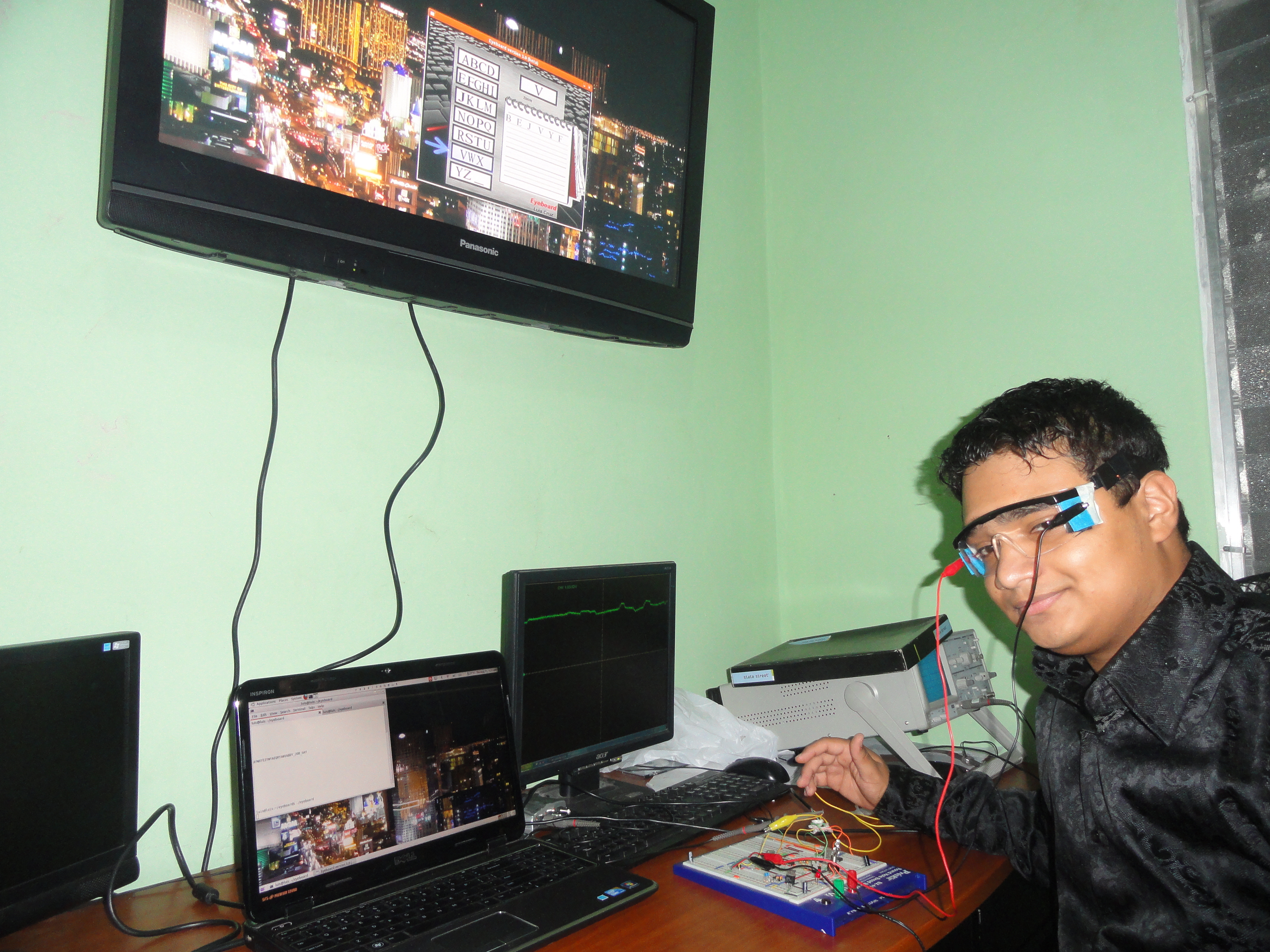
This is an inexpensive yet reliable human-computer interface that detects eye movements using electrooculography (EOG), a biomedical technique based on picking up signals from electrodes placed around the eyes. EOG interfaces let users who can’t manipulate a mouse or trackpad with their hands move a cursor on a computer screen.

An Electrooculogram or EOG is the resulting signal of the potential difference caused by eye movements. The voltage difference is measured between the cornea and the retina. The resting potential ranges from 0.4mV to 1mV and a pair of electrodes are commonly used to detect this signal, but the voltage difference when there’s an eye movement can be as small as just some microvolts. Depending on the eyes’ position, an electrode is more positive or negative with respect to the ground electrode. Therefore, the recorded signal is either negative or positive when moving the eyes.

Due to the fact that an oscilloscope or a CPU cannot detect such small voltages, an EOG system must amplify those voltages in order to get a readable signal. However, other problems such as unwanted signal (noise) arise, such as the 60Hz signal (if you are in America) caused by the AC electrical devices. Therefore, electronic filters should be used in order to attenuate noise after amplification.

The system relies mostly in three important factors: the differential voltage from the electrodes, noise, and offset. In electronics, these three “power sources” can be summed in order to estimate the output voltage.

Project Steps

Make the amplifier.

For this and other electronics steps, refer to the schematic diagram.

When working with such low voltages, amplification gain is needed, specially when working with bioelectrical signals. Differential amplifiers are handy tools when it comes to obtaining an EOG signal. A differential amplifier is an electronic filter that amplifies the difference between two voltages.

The instrumentation amplifier, INA118, is one of the best options out there for biomedical systems. Its 3-op amp design make it a powerful tool with a high gain and a high CMRR (Common mode Rejection Ratio), thus making it a perfect solution for this application. The 110dB CMRR of the INA118 (at a gain of 1000), eliminates common signals that go in both inputs, hence removing some noise.

Start by connecting the gain resistor in pin 8 and 1. Gain is calculated by the following formula:

G = 1 + (50kohm/Rg)

I am using a gain resistor of 100ohm, thus a gain of 501. After the circuit is completed, you will need to connect the electrode to PINS 3, 2 and 5 of the INA118.

Make the filters (noise reduction).

Noise reduction is the process of removing a signal that is not needed, that is, removing unwanted perturbation of a signal. Usually noise comes at a high frequency so it’s more likely that you’d need low-pass filters in an EOG system in order to block higher frequencies. A low pass filter is a filter that passes low frequency signals but attenuates signals with frequencies higher than the determined cutoff frequency. The cutoff frequency is the limit in the frequency response at which the energy flowing through the system begins to be attenuated.

The general formula I used to calculate the cutoff frequency is:

1÷[(2*pi*R1+R2…+Rx*C1+C2…Cx)^(1/n)]

Where R is the resistance used in the filter in ohms, C is the capacitance in Farads, and n is the order of the filter, or the number of reactive components used in the filter (the number of capacitors). 2π is the change from Radians to a full cycle; the cutoff frequency is thus represented in Hertz.

On this project a second order filter was used. For simplicity’s sake and to achieve a better filter, two passive low pass filters were put in cascade, both with a cutoff frequency of around 16 Hz:

1÷[(2*pi*100kΩ*0.1μf)]

1÷[(2*3.1416*100000Ω*0.0000001F)] ~ 15.9Hz

Remove the DC bias.

There’s a resting potential between the eyes. This “constant” voltage varies depending on several factors such as light, eyes’ size, skin conductivity, etc.

After the amplification process, the resting potential is as well amplified, but it is something not wanted on the EOG signal. On this project the system should be able to read the eye horizontal movements and it’s therefore measured as a signal with a slope. To remove the unwanted DC offset and to be able to read just the slope in the waveform, a small capacitor is added.

The current (measured in Amperes) that passes through a capacitor is defined by:

I = C * dv/dt

The current is defined as the capacitance times the rate of change of the voltage that passes through a capacitor, hence when the derivative of the constant potential is zero (the derivative of a constant value is = 0 ) the voltage after the capacitor is going to be equal to zero.

Voltage Follower and Dual-Polarity Power Supply

The voltage follower circuit enables you to connect a higher source impedance device than the EOG output’s impedance. This is useful to connect an oscilloscope/multimeter or any other device used for troubleshooting. This is used with a gain of zero.

An operational amplifier needs an offset so it can work correctly, especially in this case while working with negative and positive voltages. Adding a simple offset would make the reading unstable because of the fact that the resting potential in the electrodes is not constant but depends on several environmental factors.

To solve this issue, op amps need to work with a dual polarity supply, that is, positive and negative voltage with respect to virtual ground. To lower costs and complexity, I used a little “trick” to solve the offset problem, adding a couple of 7805 voltage regulators to eliminate the need for a dual power supply.

The idea is to adjust a virtual ground with two 7805’s, having 10 volts as an output, and 5 Volts in the middle set as virtual ground with another 7805, thus having a +5V, and a -5V, with respect to virtual ground.

Software: Programming the MCU

Being able to monitor the EOG signal on an oscilloscope can be pretty cool, but that’s just the beginning of what the real purpose of the project is.

In order to read the slope of the waveform when the eyes are moved horizontally, I am using the ADC of an Atmega328P microcontroller and sending that data to the computer using the serial port. A Python script then reads the data and sends it to a C++ graphical user interface where the user can choose letters with simple eye movements.

In order to read the EOG signal, the microcontroller should be programmed as an ADC and then you should be able to send that data to the computer.

If you are using the USB-Serial cable included in my kit (you can also get it on the nerdkits website, go to my website and look for the NerdKits’ store link in the external links section), and a microcontroller with no bootloader, start by burning the bootloader with an ISP programmer or use the following “hack”:

Use the parallel port to burn the bootloader into the MCU.

To program the MCU with the bootloader included, remove the wire on MCU pin 1 (the RESET line), and plug the parallel port wires in as follows:

* LPT pin 1 ==> MCU pin 19 * LPT pin 2 ==> MCU pin 17 * LPT pin 11 ==> MCU pin 18 * LPT pin 16 ==> MCU pin 1 * LPT pin 19 ==> GND

After that, you can go into the “bootloader” directory, and type “make”. Hopefully, you’ll get a successful verification from avrdude.

Install avrdude, gcc-avr, and avr-libc. Use apt-get or your favorite package manager to install them (if you’re on Linux).

If you are on Windows, Win-AVR contains a suite of programs that make programming the Atmel chip easy. The installer will install gcc on your computer which you can use to compile the C code.

Connect pin 14 to ground (PROGRAMMING MODE). Connect the yellow cable to pin 2, the green cable to pin 3, the black cable to ground and the red cable to +5V.

Connect the cable to the computer, and if you are on Windows you need to check what COM port the USB cable loaded as. Go to the Device Manger from Control Panel. Expand the Ports (COM & LPT) section. It should be COM5, COM6 for instance.

You need to open the Makefile in a text editor and edit the line that begins with AVRDUDEFLAGS. At the end you need to change “/dev/ttyUSB0” to “COM5” or whatever number it was set to. For Linux users “/dev/ttyUSB0” should work.

Make sure that the cable is connected to the computer correctly, and the switch is up. Disconnect the power supply and reconnect it to boot into programming mode.

When the kit is turned on with the switch in the UP position, it knows that it will listen for a new program. When the switch is down it just runs the program already on the chip.

Now compile the program! Open the command line to program the chip, list the files in the directory where the software is located, and type “MAKE”. If it compiles successfully, one of the last lines should read “avrdude: — bytes of flash verified” where — is some number. This means that avrdude has successfully written the program onto the MCU.

Test it.

Now that you have built the circuit and compiled the software into the chip it is time to try it out!

Paste the electrodes next to the eyes (left and right eyes), and paste the ground electrode on the forehead or in the hand (it just needs to be a neutral point).

Use alligator clips to connect the electrodes to the circuit. Now connect the right electrode on pin 3 of the the INA118P, and the left electrode on PIN 2 of the chip. The ground electrode goes on pin 5.

Make sure the system is connected to the computer. Then turn on the circuit, open the program (the board with the alphabet) and go to the command line and type “Python eog.py” to open the Python listener that will read the data from the serial port.

You should be able to control the program with the eyes. Try moving the eyes right and left, and see how it goes! If everything was done correctly, you should be able to move the arrow down with left eye movements, and you should be able to choose the letter with right movements. If there is something wrong check that everything is connected correctly including the electrodes, and make sure that there’s not too much noise affecting the signal (an oscilloscope might be helpful).

A program to adjust the system without an oscilloscope will be available for download on my website soon!

EOG Glasses

The EOG glasses offer a more comfortable interface while using the system. They are homemade glasses that hold the electrodes. I am using foam, a head band and super glue.

I have built several prototypes of EOG glasses with good results.

Using the Eyeboard

To choose one of the letter boxes, the user moves the eyes to the left until the box is chosen.

While inside the box, a letter can be chosen with right eye movements.

Conclusion

I'm still improving this EOG system, including looking for ways to make it more comfortable to wear. I’m pleased to have developed a system for less than $200 that enables disabled people to communicate, when commercial versions of the same cost a minimum of $10,000.

This project was the subject of an article in MAKE Volume 29, page 60.