To celebrate 20 years of Make:, we’re looking back at projects from our first issue. Combining the power of five cables in one easy-carry package, here’s “5-in-1 Network Cable” from Make: 01.

Note: this is a classic article. Some of the information is likely obsolete.

This project appeared in Make: Vol. 01.Subscribe to Make: for more great articles.

Why I made a 5-in-1 cable

Do you find yourself toting several of these cables everywhere you go? Do you often wish you’d brought a different cable with you after you’ve arrived onsite? Are you as geeky as me and think that the idea of a 5-in-1 is just plain cool even if you never expect to configure a router in your lifetime? Then I’ll show you how I made one.

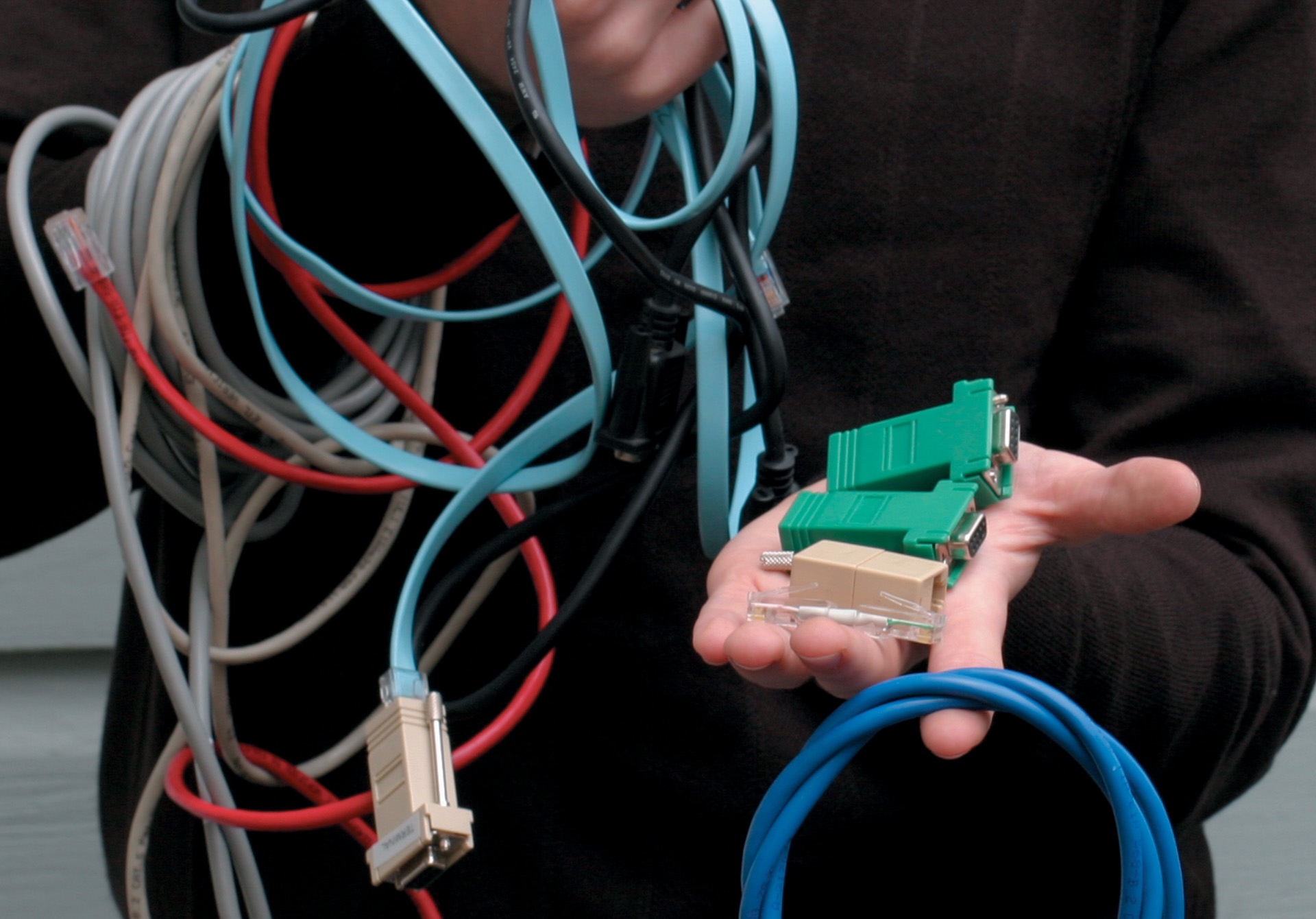
The 5-in-1 cable consists of a CAT5 Ethernet cable along with four simple custom adapters, giving me an Ethernet cable, a crossover Ethernet cable, a modem cable, a null modem cable, and a Cisco console cable. An added benefit is that I can always extend my cable by finding a longer Ethernet cable than the one I carry in my bag. (It’s usually pretty easy to locate a long Ethernet cable, but not so easy to locate a long null modem cable.)

Illustration by Nik Schulz

Set up

Full tools and materials info in the sidebar

What will the next generation of Make: look like? We’re inviting you to shape the future by investing in Make:. By becoming an investor, you help decide what’s next. The future of Make: is in your hands. Learn More.

Project Steps

1. Make “the world’s shortest crossover cable”

You can actually make the crossover cable as long as you want, but the longer you make it, the more you have to carry around.

This cable must cross the pairs that are not used by Ethernet in addition to the pairs that are. This is why you must perform this critical step and cannot use a standard crossover cable you may already own.

1a. Crimp one of the RJ45 plugs on each end. Order the wires on one end according to the following 568B standard (with the clip facing down):

This is the most common order for Ethernet cables, so you could get a head start by snipping off the end of an existing cable; then you only have to do the other end.

1b. Order the wires on the other end this way:

Make sure each pair has at least one twist. Then you can prove people wrong if they scoff, “That’s not the world’s shortest crossover cable; that’s just an adapter!”

2. Make the cisco console adapter

This adapter works with the RJ45 serial port found on most Cisco routers. It also works on some Sun servers. It is important to note that this is not a symmetric adapter. The 568B end will point away from the router and the other end will be inserted into the router. I marked one end with a Sharpie so I wouldn’t forget which end was which.

Cisco’s (otherwise very helpful) cabling page has RTS and CTS reversed on the DB9/RJ45 console cable. I verified this by inspecting an actual Cisco cable. They don’t really care because their console ports do not use flow control, but doing it the right way enables interoperability with Sun servers and perhaps some other things.

This is like the crossover cable but with a different pinout.

2a. Make the first end according to 568B again (clip facing down):

2b. And the other end:

Since this is an asymmetric adapter, mark one end of the adapter with a Sharpie so you know which end is which.

3. Make two DB9/RJ45 adapters

This is the trickiest part. In order to make your cable compatible with the largest number of serial devices possible, you need to combine a couple of pins and split another one. Both of the DB9/RJ45 adapters should be wired exactly the same way, regardless of whether they will be used for DTE or DCE devices. Here is the pinout:

* My DB9F/JR45F modular adapters are colored blue, orange, black, red, green, yellow, brown, white (RJ45 1-8). If yours are different, ignore the colors in the above pinout.

3a. DB9 pins 2, 3, 4, 7, and 8 are easy. Just push the appropriate pin in the back of the DB9 connector until it snaps.

Be careful not to get any of the pins mixed up because errors are a bit difficult to fix unless you have the right tool to pop the pins back out again.

3b. DB9 pin 5 needs two wires connected to it. Snip the pins off of the wires coming from RJ45 pins 2 and 6 (orange and yellow on mine), strip about 3mm off the end of each, and crimp them together onto one of your spare pins.

Use a spare pin to crimp the wires together.

3c. RJ45 pin 8 has to connect to both 1 and 6 on the DB9 connector. Snip the pin off of the white wire, strip the end, cut about an inch of scrap CAT5 and pull out two of the white wires, strip both ends off of them, crimp a pin on each one, and splice all three loose ends together.

You can break the end off of a spare pin and use it to crimp the three wires together. You can use the other two white wires from the inch of CAT5 for the second adapter.

Conclusion

Putting your 5-in-1 cable to work

Need a different pinout?

If you need a DB9/RJ45 serial cable with different pinouts than the Cisco one, all you have to do is make another little CAT5 adapter. Cable ends are cheap and plentiful.

Faking flow control

When used as a serial cable, this is a hardware flow control (CTS/RTS) cable. If you are using devices that both require hardware flow control, it should work. If neither of your devices requires hardware flow control, it should still work. However, if one of your devices requires hardware flow control and the other does not support hardware flow control, then you need a cable that fakes flow control. This could be done with an additional DB9/RJ45 adapter or with another CAT5 adapter and some creative crimping (my preference), both of which are left as exercises for the reader.

Extra adapters

Many additional adapters could easily be added to this set. A few that leap to mind would be for other kinds of serial ports such as DB25 and various DIN and miniDIN ports for Macintoshes and other things. For the pinouts for these adapters, please visit my website.

Check your conductors

If you grab a random Ethernet cable to use with your serial adapters, remember to make sure that it has all eight conductors. Also keep in mind that most Ethernet cables have only been tested for connectivity on four conductors (1, 2, 3, and 6) if they have been tested at all. I used those conductors for the most important serial signals (Transmit, Receive, and Ground) just in case, but some serial devices won’t talk without all eight working.

Photos by Michael Ossmann. This project appeared in Make: Vol. 01. Subscribe to Make: for more great articles.