Have you ever wondered what information is stored on the magnetic-striped cards in your wallet? Now you can find out. This project shows you how to make a magstripe reader for less than $40.
is a computer science major at Georgia Tech, who has written and lectured about privacy and security. He is the creator and lead developer of Stripe Snoop.
To celebrate 20 years of Make:, we’re looking back at projects from our first issue. In this project from Make: 01, readers learned how a magnetic stripe reader works and how to read information on their own cards.
Note: this is a classic article. Some of the information is likely obsolete.
This article appeared in Make: Vol. 01.Subscribe to Make: for more great articles.
What’s on your credit cards?
Open your wallet. How many cards in there have magstripes on them? If you’re like me, the answer is five or six. Ever wonder what’s encoded on them?
I did. One day a friend of mine had a $200 off-the-shelf magstripe reader, so I ran my cards through it. Aside from the expected credit card numbers, I was surprised by the amount of personal information encoded on them. In fact, for reasons I still don’t know, two cards contained my Social Security number.
Illustration by Timmy Kucynda
Magstripes are everywhere in the developed world, but aside from a few academic papers and hacking articles, very little information is published about them. So I looked into it and ended up designing my own magstripe reader, interface, and software. This project shows you how I did it, and how you can, too.
Tools and materials
Not all items are shown in the image above
Project Steps
Building the basic magnetic stripe reader
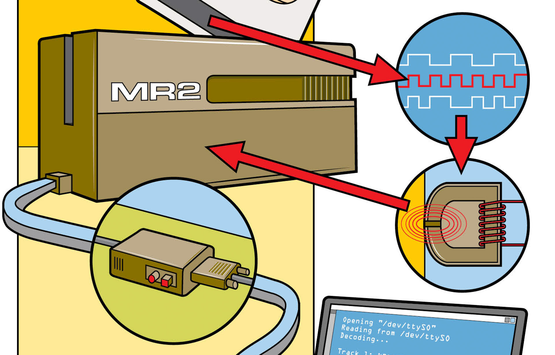
The central component of our project is a TTL magstripe reader. You don’t want one that’s advertised as being serial, parallel, keyboard, or USB based. Fortunately, TTL (also called “clock/data”) readers are much cheaper than other readers because they don’t contain circuitry for processing card data.
A TTL reader has three outputs: a card-present (CP) line, which lets you know when a card is being swiped; a clock (CLK) line, which goes high when the DATA line is valid; and a DATA line, which delivers a stream of ones and zeroes representing the data on the card. You will wire these signals to the pins of the game port. These pins are the same pins that joystick buttons use.
Basically, this reader “fools” your computer into thinking it is processing the activation of joystick buttons. First, the CP “button” is “pressed.” Then the CLK button is pressed, which saves the state of the DATA button. This allows the Stripe Snoop software to capture the entire bitstream contained on the card and decode it.
1a. Prepare the connector. The first step is pretty easy. Take the DB-15 male connector and place it in your helping hands. Take a wire from your jumper wire kit and place it in the other helping hand. Maneuver the wire so that it sits in the hollow part of the pin, and solder the end to pin 2. Repeat for pins 4, 7, 14, and 15. Pins 4 and 15 correspond to ground (GND) and 5V, respectively, while pins 2, 7, and 14 are the buttons used by joysticks. It’s easy to get turned around and forget which pin is which. Use a permanent marker to label the pins.
If you’re new to soldering, be sure to check out our Primer article, Soldering & Desoldering, p. 162.
Next, cover the pins with hot glue to ensure the wires can’t pull loose or touch each other.
1b. Wire up the TTL reader. Use a knife to carefully remove the side panel that covers the Omron V3A-4’s circuit board. Cut the farthest right tab off of the cover (the tab the knife is pointing to in this picture). This hole is where our wires will come out.
1c. At one end of the circuit board you should see a row of nine metal contacts. We will be soldering wires to pins 1, 2, 4, 5, and 6 (Contact 1 is at the bottom and 9 is at the top as seen here). These contacts are rather small, and it’s easy to put down too much solder and short two of them together.
1d. Go slowly and make sure not to use too much solder. Check neighboring contacts as you go to make sure they don’t touch. Also check to ensure that you can see the white line in between them. If not, use the soldering iron to heat both contacts, remove the excess solder with a solder sucker, and try again.
This is the hardest part of the project. If you keep shorting the contacts together, try using the soldering iron to melt a small amount of solder onto the contact. It should bead easily and not touch the neighboring contact. Now, holding the wire in one hand and the soldering iron in the other, heat the bead of solder and push the wire into the liquid metal.
1e. Once each wire is soldered, carefully bend it 90 degrees and position it so that it exits the back of the reader where we previously removed the tab from the side cover. Use the hot glue gun on the bent wires when you are done to make sure they don’t pull loose. Be careful that you don’t use so much glue that you can’t see which wire is soldered to which pin. It is useful to fan out the wires (as shown) to keep the order correct.
Be careful bending the wires to ensure that you don’t pull apart the soldered connections. Use a pair of needlenose pliers to hold the wires steady at the solder joint before bending them with your fingers.
1f. Connect the reader and connector. The hard stuff is behind us. Now we simply join the DB-15 connector and the reader. Take your four-foot piece of Cat 5 cable and pick five wires you want to use. I recommend using all four of the solid color wires, and one of the striped wires. Strip off about 1.5 inches of insulation from each end. Cut off the three wires you are not using so that they don’t get in the way, and strip a quarter-inch off each of the five wires you are using. Do this to both ends of the cable.
We are going to connect the pins of the TTL reader to the pins of the DB-15 connector as indicated below.
1g. Use pliers to make small hooks at the end of each wire coming from the reader, connector, and cable. Hook the correct wires together and use a little bit of solder to secure them.
Use a small piece of electrical tape to protect each junction. Once complete, use more electrical tape to strengthen the transition at each end of the Cat 5.
While this step is not technically demanding, it is quite easy to make a mistake. It is very important that you solder the correct wires together. For each connection, I would solder one end of the jumper wire to the reader and the other to the DB-15 before moving on to the next wire. This helps prevent mistakes.
Zip ties and heat-shrink tubing can help clean this up and make it look more professional.
Building a parallel port adapter
So what do you do if your computer doesn’t have a game port? Well, as long as you have an available parallel port, you can build a simple adapter that allows you to use the reader we have constructed.
The adapter makes use of the five inputs used by printers to report errors to the PC. Instead of checking if the CLK joystick “button” is pressed and saving the status of the DATA button, we are checking to see if the printer is out of paper, and then saving the status of the acknowledge pin. We use a buffer/line driver chip between the game port and the parallel port to protect against future readers that might produce too much current and damage the parallel port. We also need a 5V power supply because the parallel port doesn’t have one.
2a. Prepare the project box. Use a Dremel tool to cut the holes in the project box. I’ll refer to the face where the metal plate goes as the top of the box. Place the box top down, so you are looking at the bottom face, with the short sides to the east and west. On the east side of the bottom face, drill a 1" hole. This is for our battery leads.
This is going to be messy! Do this in a place that is easy to vacuum. Wear eye protection against the flying plastic pieces.
Now, on the west face of the box, near its edge with the bottom face, cut a hole for the DB-15 connector. It should just fit between the two screw posts. Remember: don’t glue any of these components in yet!
On the south face (a long side), near the edge it forms with the bottom face, cut a hole for our DB-25 connector. We want this hole to be close to the west side of the face, about ½" from the edge the south and west faces make. Again, use the Dremel to cut a hole and then shape it until the DB-25 connection fits.
Finally, we need to cut holes for our power switch and power LED. These go on the east face, near the edge the east and bottom faces make, Drill a 1" hole for the LED’s wires, and use the Dremel to make a small hole for the power switch.
2b. Prepare the connectors. Next we need to prepare our DB-15, DB-25, power switch, and LED. Since these components will be mounted to the project box, it’s important the wires we solder to them are long enough for us to comfortably solder them to the circuit board. You should use the longer wires in the wire kit. We are going to solder long wires (the red wires are a good length) to pins 2, 4, 7, 10, 14, and 15 on the DB-15 connector. After you’re done, use the hot glue gun and cover all the pins and wires.
The pin numbers on the DB-15 female connector are the reverse of the male connector. Use a permanent marker and note which pins are which! Do the same for the DB-25.
Solder wires to the DB-25 pins 10, 11, 12, 13, 15, and 25. Again, use the longer wires to give yourself enough slack. Use the hot glue gun to cover all exposed metal on the back of the connector.
For the power switch and LED, solder wires to the leads on both. Make sure you remember which wire is attached to the shorter lead on the LED. This wire will later be connected to GND.
2c. Make the power supply. The power supply should be located on the left side of the circuit board. Don’t worry about soldering on the battery leads yet, so be sure to leave some space to the left of the power supply. Use the shortest wires from the wire kit: red, orange, yellow, and green. When connecting components, twist the leads together using a pair of needlenose pliers. The circuit is rather straightforward, as shown in the diagram.
There are a lot of connections to the power supply’s outputs (especially GND) so leave room around them. Try not to have more than four wires at each junction. As you need to, use short red wires to extend a junction for additional wires. Note that the lead on the capacitor closest to the off-color stripe, or the lead that is the shortest, should be connected to GND.
Hint: If it makes you more comfortable, build this circuit on a breadboard first. Then implement it in stages.
2d. Attach the octal buffer, final preparations. With the power supply on the left of the circuit board, place the 74541 chip on the right side of the board, with about five holes open to its right. You should also place the chip upside down (pin 1 at the bottom). This places our input pins (pins 2-5) on the right, where the DB-15 connector will be.
Solder the 5V and GND wires to the pins as shown. Attach the resistor to a 5V line and leave the end open. We will connect this to our power LED.
Bend the unused pins on the 74541 to help hold the chip to the board while soldering. Just make sure you don’t let any of them touch.
2e. Final construction. Now we attach the wired connectors to the circuit board. Push the power switch into its hole, with the wires going into the box. Use hot glue to secure it in place. Do the same with the LED. Slide both leads from the battery-clip thru hole in the bottom face and solder the black wire of the battery clip to the GND input of the power supply. Solder one end of the power switch to the 9V input of the power supply and the other to the red wire of the battery clip. Solder the wire on the short side of the LED to the GND and the other to the resistor.
Next, glue the DB-25 connector into place. Solder the pins to the correct pins of the octal buffer using the circuit diagram. Remember, the octal buffer is upside down; all the DB-25 wires should connect to the side of the chip facing the power supply. Solder them according to the diagram.
Finally, slide and glue the DB-15 connector into place. Things are probably getting crowded, so use needlenose pliers to help move the wires into position. Solder them according to the diagram.
Don’t use too much glue with the power switch, or you could glue the switch into one position. Things will get difficult as you attach the wires from both DB connectors. Make sure in all the mess you don’t short anything out.
Usage and notes
Sometimes, if the adapter is connected to the parallel port and the battery is not connected, the power light will still be on. I’m still not entirely sure why this happens. Depending on the amps needed to run your reader, it may even function. However, to guarantee the results, use a battery. The circuit will also operate without a buffer chip. However, it’s better to fry a 50-cent part than your parallel port. Use the chip.
Please note
A black box with wires coming out of it, a switch, and a red light tends to worry airport security. You have been warned!
Conclusion
Using the Stripe Snoop software
Stripe Snoop, released under the GPL, is a program for both Linux and Windows. While it is command-line based, GUI front ends are in a preliminary development stage. Installation is very straightforward and the program comes equipped with a lot of documentation that is also available on the website.
A few notes and limitations: due to the way Stripe Snoop accesses hardware, you will need to run it as root if you are running Linux. Due to the polling nature of the game port, please run Stripe Snoop on a machine faster than a Pentium 200 that isn’t heavily loaded with other programs. Currently, Stripe Snoop is only functional on x86 architecture although a USB-based reader is in the development stage.
There is a simple program, rdetect, which will help configure Stripe Snoop for your reader. Once setup, run Stripe Snoop using the command ss. When prompted, swipe your card. Using different ISO standards, Stripe Snoop will try to decode the bitstream it captures from your newly built hardware interface and display the data to the screen. If the card is in its built-in database, it will supply more meaningful information to the screen than just the raw data stream.
For instance, the stream “4313012345678901= 05061010000565” would be decoded by Stripe Snoop as a Visa Credit Card issued by MBNA with such-and-such credit number and expiration date. Stripe Snoop has several features including a raw mode, which allows you to see the card’s bitstream, and a force mode, which will (try to) parse damaged magstripes. There are several other options available, and I encourage you to read the documentation.
You can read all three tracks on your cards by making simple shims to insert into the card stripe reader. Find out how to do this on my website.
Future project ideas
Cola machine
Now that you have a system to read an account number from a card, causing an action based on the account number is the next logical step. I built a cola machine that releases soda using motors and relays when its reads my student ID. This is certainly a fun project, and shows how magstripes can function in a larger project.
Power LED
Is this thing on? A power LED built into the reader is fairly easy to do and very helpful. Perhaps you hook it up to the parallel port and use it to provide feedback about a swipe (blink if it didn’t parse, green if good, etc.).
Toss the PC
There’s no reason you have to use a PC and Stripe Snoop to decode the magstripe. PIC, BasicStamp, and other microcontrollers are perfectly capable of doing it, too. This will help keep your project small. If you do need to use a computer, there is an older DOS version of Stripe Snoop that can run on a 386, and I’ve gotten the Linux version to work on a 486 running Slackware. Visit Stripe Snoop’s homepage for information on the magstripe standards and source code.
USB Reader
What about a USB-based interface? A simple microcontroller to collect all the information and a cheap USB chipset could be the basis of the next generation of readers.
Photos by Billy Hoffman. This article appeared in Make: Vol. 01. Subscribe to Make: for more great articles.
is a computer science major at Georgia Tech, who has written and lectured about privacy and security. He is the creator and lead developer of Stripe Snoop.