When I read the Geekcon 2010 call for projects, I thought, what the hack — I’ll do it. Inspired by Julia Cameron’s The Artist’s Way, I decided to let creativity into my life, and start inventing things.

I watched Sterling Johnson’s magnificent “Giant Stinson Beach Bubbles” clip on YouTube, and when I described it to my neighbor Yuval, he suggested that I combine bubble-making with Arduino, which I had been playing with. Bam! That was all I needed. I submitted the Bubblebot project idea, and it was accepted to Geekcon, where I had the exciting experience of collaborating with all these bright people and watching the design manifest from their suggestions.

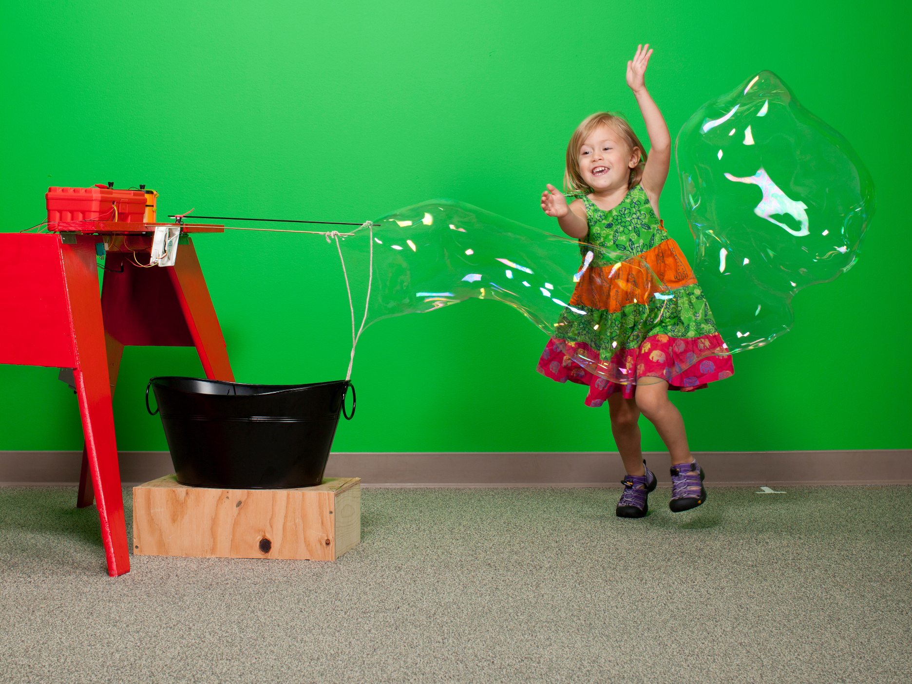
People typically blow giant bubbles through a loop of absorbent cord held between two sticks. On my Bubblebot, the sticks attach to a hinged shelf that a gearmotor tilts down and back up by reeling fishing line tied to a lever. After each dip, a servo spreads the sticks and a fan blows air through the loop.

Since Geekcon, I’ve built two more versions of the Bubblebot, written an Instructable about it, presented it at a local festival, and gotten many great responses to it from both adults and children. I’ve also learned that making gigantic soap bubbles under diverse wind and weather conditions requires a human touch and intuition that two motors and a fan can’t imitate consistently.

I recently added an arcade-style console for remote manual control. Whenever the Bubblebot is switched from automatic to manual mode, a siren sounds to alert everyone nearby that the bot will now be driven by a human rather than by a flawless microcontroller. You have to see people’s reactions when this happens.

Project Steps

Set up the frame.

Start with a sawhorse or similar frame. Take the 1×4 shelf, measure about a third of the way down from the right side end, and saw a rectangular notch that exactly fits your servo body lengthwise. The servo will hold one of the cord sticks, and we’ll call this edge of the shelf the front.

It probably makes more sense to buy a sawhorse, unless you enjoy just about any kind of woodworking (like me) — in which case, check out how I built mine.

Attach 2 hinges along the back edge of the shelf, one at each end. Similarly attach the other sides of the hinges to the top of the sawhorse’s crossbeam, making sure that the shelf can swing 90° down — from flat horizontal to perpendicular to the ground.

Drill pilot holes for the screws to prevent the wood from cracking.

Along the front edge of the shelf, drill 2 pilot holes in the middle for attaching the fan, and another hole just past the fan mounting holes (opposite the servo notch) sized for the fixed cord arm. In the back edge of the shelf, drill a hole sized for the tilt lever about 2″ from the end nearer the servo notch.

Mount the fan angled down somewhat, so that it blows underneath the arms where the loop will hang.

Add bubbling subsystem.

Place the servo in its notch, drill pilot holes for the supplied screws, and screw securely in place.

Level the servo with the shelf so that when it tilts straight down, the servo arm is oriented up and down, parallel to the shelf.

Fit one of the cord arms into its hole in the front of the shelf. Attach the other cord arm to the servo arm using short zip ties. Instead of zip ties, you can wind thin copper wire around the joint.

Cut the cord into lengths of 2′ and 4′. You can make minor size adjustments later on, but these numbers should put you in the safe zone.

Loosely tie one end of each cord to the free end of each cord arm. Make sure you can untie the ends later for adjustment. Now, when the shelf is parallel to the ground and the arms are open, the cord should hang in a loose triangle.

Make a loose knot or tie a zip tie to the middle of the long cord, creating a smaller loop at the bottom of the main, larger one.

This small loop will help the main loop make its way back into the bucket when the arms tilt down, to prevent it missing the bucket and getting dirty (which weakens bubble formation).

If needed, you can tie a washer or other small weight to the bottom of the small loop.

Fit the tilt lever into its hole in the back edge of the shelf and tie the piece of fishing line to its free end.

It helps to file a small groove in the dowel to keep the fishing line knot in place.

Pull on the fishing line to manually test how much force it takes to pull the shelf (with arms attached) up to its topmost, horizontal position. It shouldn’t be too hard. The shelf should also fall down by itself if you let go. If not, make sure your hinges are properly aligned and oil them a little bit.

Attach the fan to the front of the shelf using 1″ wood screws. When the shelf is in its topmost position, the fan should point right into the middle of the cord triangle.

You may need to adjust the fan angle later, so don’t drive the screws in all the way yet.

Add switches and motor.

Two micro switches act as limit switches for the hinged shelf, reversing the shelf’s direction when it reaches the top or bottom of its arc.

Solder 2′ wire leads to the ground and NC terminals of one micro switch, and to the ground and NO terminals of the other. Hot-glue the NC-connected switch on top of the sawhorse’s crossbeam so that when the shelf swings up, it clicks the switch just before it reaches the top.

Hot-glue the NO- connected micro switch to the underside of the crossbeam so it clicks when the shelf hangs all the way down.

To get the micro switch positions right, it helps to glue them to small brackets cut from scrap wood rather than directly to the crossbeam.

Attach the spool to the gearmotor shaft. Mount the gearmotor to the back leg of the sawhorse on the lever side with the motor shaft parallel to the hinges.

The characteristics of the motor and spool that you use will dictate how you should mount them. Use your hacksense to come up with a good arrangement. You may need to add brackets, rollers, or other extra components.

Solder a 3′ wire to each gearmotor terminal.

Tie the free end of the fishing line around the spool (the other end should already be tied to the tilt lever) and hot-glue it down so it doesn’t slip.

Add the electronics.

Assemble the RBBB (Arduino clone) kit according to the supplied instructions, but substitute a 7805 voltage regulator for the included L4931CZ50 regulator in the spot marked “VR.” Solder the L298N motor controller to its breakout board.

Plug the RBBB into the stripboard, perpendicular to the strips underneath. Use pin headers to solder the L298N breakout board alongside it so the Arduino D6 and D7 pins connect to the L298N IN2 and IN1, respectively.

Insert the MCP23017 16-bit I/O expander chip alongside so RJ45 pins 1–7 line up and connect with the I/O chip’s pins 0–6 in reverse order (e.g. RJ45 pin 7 to chip pin 0, RJ45 pin 6 to chip pin 1, etc.). The I/O chip’s pins 12 and 13 will connect to Arduino pins A5 and A4.

If you’re making the arcade console, fit an RJ45 jack onto an RJ45 breakout board and solder pin headers to plug it into another corner of the stripboard, so that an Ethernet cable can plug in at the board’s edge.

Follow the schematic and photos to plug the rest of the onboard components into the stripboard and connect them together: the resistors, diodes, and Darlington transistor.

Drill away the copper connections at all points marked with an “X”, and between the RBBB and I/O chip pin rows.

Drill holes in the sides of the project box for connecting the off-board component wires, battery power, and Ethernet cable to the arcade console (if using).

Follow the schematic to solder wire connections out to all the off-board components, and thread the wires through the holes: gearmotor, servomotor, fan, speaker, boundary switches, and 12V battery.

Secure the board inside the box using zip ties, making sure that an Ethernet cable can both plug in and unplug from the RJ45 jack. Connect all the off-board components to their leads.

If your battery is small, you can use hookup wire to connect it to your board. With a larger one (like a moped battery), use a switched lamp cord, screwing its wires to one side of a 2×2 terminal block on the board. The other side of the block should connect to a standard 5mm barrel connector for plugging into the RBBB power jack.

If you want to connect the speaker, wire it between Arduino pin D9 and GND. With the speaker connected, the siren will play constantly while Bubblebot is in manual (controller) mode.

Attach the project box to the sawhorse top. If you’re unsure of its placement, use zip ties for now and substitute screws later.

Build the remote arcade console (optional.)

You could make the Bubblebot without the console, but you wouldn’t want to, because it’s the coolest part!

First, cut 6 pieces of plywood for the box: 25cm×27cm (2); 25cm×7cm (2); and 16.5cm×5.5cm (2).

These instructions cover 7mm plywood — with other widths you’ll need to tweak these numbers a little bit. MAKE’s test builder Max Eliaser used ¼” plywood with the following specs: 2 pieces 10″×12″, 2 pieces 12″×2¾”, 2 pieces 10″×2¼”, and 2 scraps 2″×2¼”.

On one of the large pieces (the top panel), drill a hole for mounting the switch and 2 holes for the buttons, then cut a rectangular hole in the middle for the joystick. Install the switch and the buttons with the supplied nuts, and mount the joystick with ½” screws.

Feel free to use my layout or create your own. I used a 7″ (8mm) bit for the switch, a 1″ (27mm) hole saw for the buttons, and a razor saw for the joystick.

Cut a small rectangular hole in one of the side panels, just large enough to fit around an RJ45 jack.

Glue all the wood pieces together except for the top panel to make an open box.

Under the top panel, solder a ground wire (or wires) to connect the ground/common terminals of all the buttons and the toggle switch, and one leg of each joystick direction.

Solder individual wires to the power-side contacts for all the controls (with 3-pin buttons, solder to the normally open pin). Solder an RJ45 jack to an RJ45 breakout board, then connect all the wires to the board as shown in the schematic.

These pins will all be pulled up by the MCP23017 16-bit expander chip and will read HIGH on the Arduino when not activated.

For covered switches with built-in LEDs and 3 pins, ignore the ground pin and solder leads to the Power and ACC pins. The LED won’t light up, but the switch will still work.

Glue the RJ45 jack into the hole you cut for it in the side of the box, then close the box.

Voilà! You’ve just built a multipurpose arcade console that you can use in many projects to come.

Program and test.

Download and install the Arduino environment (from arduino.cc) if you don’t have it already.

Download the project code files BubbleBot_MAKE and ArcadeControllerTester.

Plug the programming cable between your computer and the microcontroller, and upload the BubbleBot_MAKE sketch.

First, test the Bubblebot in automatic mode. Disconnect the programming cable and power up the Arduino to do a dry run without bubble mix.

Watch the arms and do a program-test loop, modifying the servo boundary values arm_open_pos and arm_closed_pos at the top of the code, until the cord loop dips fully into the container and stretches out into a nice triangle.

To test the arcade console (if you made one), plug the cable between it and the control box. Connect the RBBB to your computer and upload the ArcadeControllerTester sketch.

Open the Serial Monitor and try out all the controls while watching the Serial Monitor outputs. The outputs should match the control inputs; for example, you should see UP when you push the joystick up.

Conclusion

Bubblebot Operation

Combine the ingredients for the bubble mixture and let it stand for 24 hours, ideally in a refrigerator. Fill a tub, place it below the Bubblebot, and power it up.

Watch how it works, and make adjustments by modifying the source code (speed and duration of arms spreading, number of spreading iterations), by raising or lowering the tub, or by setting up in different locations.

Tips for Happy Bubbling

  • Pick a humid day, as cool as possible.
  • Avoid direct sunlight on the bubbles.
  • Pick places with steady wind flow or operate indoors. If you want to try for stronger wind, substitute a car fan for the computer fan, and experiment with different fan positions.
  • To focus the air more efficiently into the cord loop, add a paper duct in front of your fan. Just roll up and tape a piece of printer paper or cardstock about the same size as your fan’s blade circumference, then tape this duct to the fan.
  • Decorate your Bubblebot! I added color to mine by slitting foam pool noodles along their length, about 2/3 of the way deep, wrapping them around the sawhorse legs, and securing with zip ties. I cut and applied more noodle foam to other wood surfaces using hot glue.