DIY Pickup Winder
Photography by Janmeja Heir

This project for me came about as just a step on my way to building a guitar. While most electronics in a guitar consist of basic, inexpensive components, a good pickup can be pricey. Its construction is also one of the biggest factors in how your electric guitar will ultimately sound. Building your own pickup is not only a fun learning project, but it also gives you the ability to fine tune the sound of your guitar and build your own unique tone.

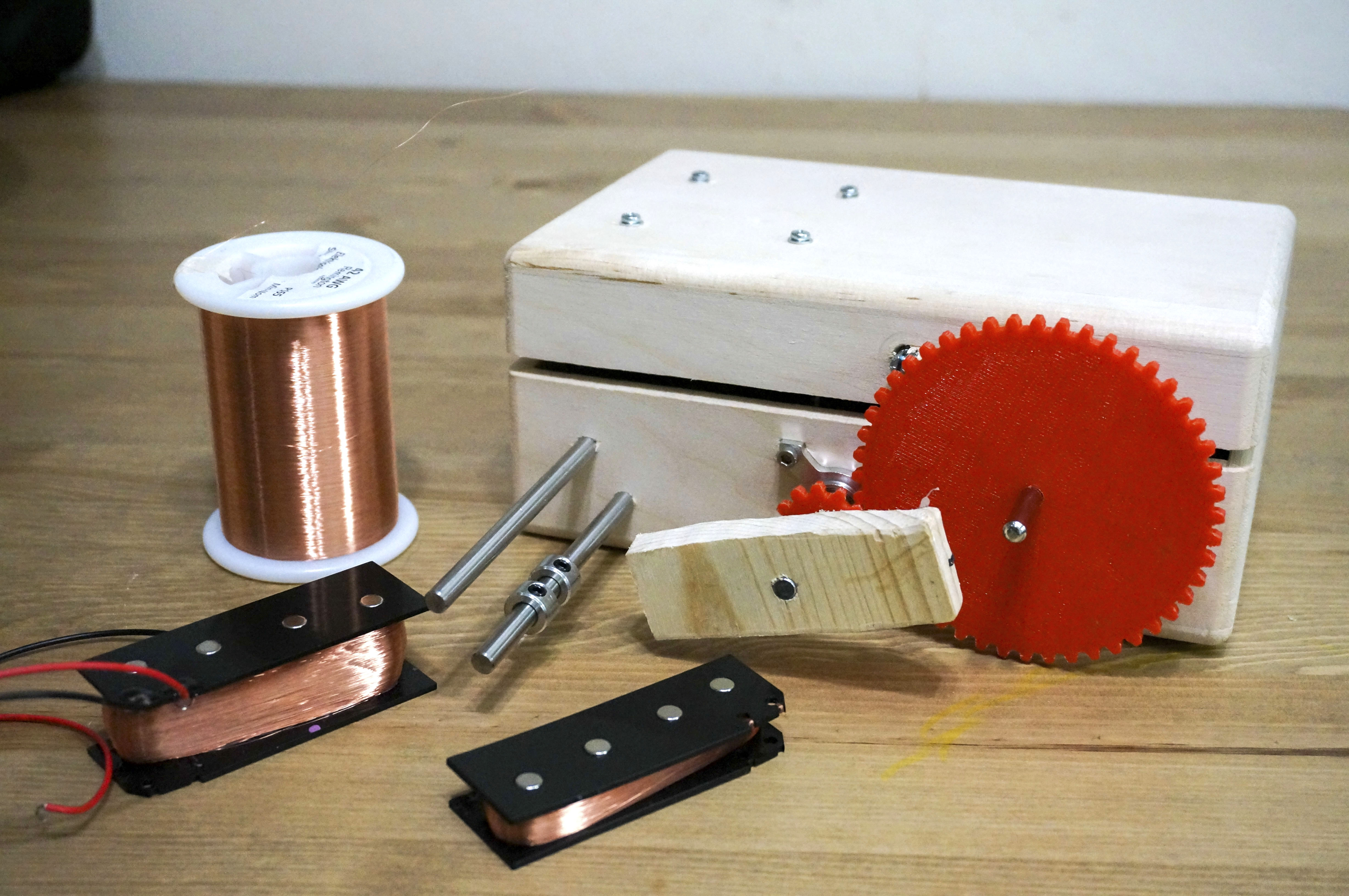
A guitar pickup is an amazingly simple device that consists of wire wrapped around a magnet. There are of course an infinite number of combinations in how that can happen, but ultimately if you just manage to get a wire wrapped around a magnet enough times, you’ll have a pickup.

Fortunately, the pickup winder outlined in this project makes the basic process quite simple, freeing you up to experiment. Remember that a lot of the early distortion effects were based on sounds that happened when amps and speaker cones were damaged, so clearly doing things “the right way” is not necessarily what is going to give you the sound that you want.

YouTube player

Please note the gears required for this project. I could not find pre-made gears big enough to use with the counter, so I created my own. I’ve uploaded files for 3D printing and laser cutting. For my first test, I laser cut gears from acetal. The version shown here is 3D printed. Both worked fine. You can also use a sprocket and chain set, available at Servocity. Just needs to be a 0.25:1 gear ratio, the counter moves at ¼ speed.

The counter has a max speed of 350 RPM, so you could potentially use up to a 1400 RPM motor with this same setup. If you would like it to go faster, I would suggest using a chain and sprockets, available from Servocity. They have a broad range of gear ratios available, enabling up to around 2100 RPM motors to be used.

Using your Pickup Winder

For attaching the pickup, I used a thin double sided tape that I had sitting around from repairing screens on a cell phone. It worked reasonably well, though I think maybe a bit thicker of tape would be better. There is also a putty that is used for pickup winding, though I have not tried it.

Winding pickup
A view of how the pickup sits in the winder. This photo was from my first build, which wasn’t as pretty.

When you begin winding, start with the collars very well within the limits of your bobbin. Do the winding slowly at first, moving the wire to the edges of both collars. You’ll probably have to pause and adjust the collars out a couple times before you get it to fill the bobbin properly. Make sure that you don’t go too far, a bit of empty space at the edge will end up getting filled from jitter, but it just takes a fraction of a second of the wire going past the edge to mess up your coil.

Pickup Winder

Before winding, thoroughly wash and dry your hands. Any bit of moisture or anything on your hands can get the wire caught enough to snap as it gets pulled through. You should also start with a practice bobbin — the first few times you’ll need to figure out how much tension to apply and how far the collars need to be adjusted.

Winder Close Up

If you would like to reduce cost of the build, a few parts can be changed or omitted. The PWM controller is helpful, but it can function without. Also the counter and gears are helpful, but you can also omit them and just monitor DC resistance as you wind. The box I used fits pretty well, but just a bit of hobby wood from a hardware store would be cheaper and could be cut to fit.

Finished pickup
A finished pickup, ready to install in my guitar.

Project Steps

STEP 1: MARK ALL SPOTS FOR DRILLING

On the side of the box that opens, lay out the ball bearing mount, gears, pickup mount, and guide bars as shown in the photo. I used standoffs as place holders for the guide bars just to help with positioning. You’ll need to make sure the space is sufficient for the gears to connect properly and also have room for the counter inside the box.

The bottom screw holes for the channel/ball bearing mount need to be 0.22” from the wall, but it’s okay to have it placed a bit further from it.

Part layout for marking

The guide rail closest to the pickup mount should be placed fairly close to reduce the amount of jitter possible on the wire before it makes contact with the pickup. Remember we’re going to have the motor spinning counter clockwise, so the wire being fed through doesn’t make any sharp angle changes. I’ve found that having the smooth transition and two rails helps be able to put proper tension on the wire with minimal chance of breaking it.

A note about the gears: I’m using them because the max RPM of the counter is well below the speed of the motor. The 0.25:1 gear ratio here gives us one full count for every four turns the drive shaft makes. So if you want to get 4,000 coils on the pickup, you would wind it until the counter read 1,000.

Space for counter
Make sure that you have enough space inside the box for the counter — the box I used was a pretty tight fit. I just put marks on the lip of the box, it’s too close to really have a regular hole drilled.

Also, remember the reset counter arm needs to have enough room to swing up to reset. I actually bent the arm with pliers so that it wouldn’t hit into the side of the box. I would also suggest making a mark on the lid side of the box, about level with the ball bearing mount. This will be used to put the speed dial for the PWM controller through.

PWM Controller

Once you’ve marked all of the locations to be drilled, flip the box over to the top and mark the holes for the PWM controller. This will be mounted inside of the box, so make sure to place it low enough that it will not hit into the motor when closed.

Hole for Power Jack

Finally, on the side of the box with the hinge, mark a hole for the power jack.

STEP 2: DRILL HOLES

Once you have everything marked, drill your holes out. With the box I used, the counter was very close to the edge of the box so I just cut a chunk out from there. I also did not have the right size bit for making screw holes, so I just went bigger. It will be secured on the other side of the box, they do not actually need to fit snugly into the wood.

Drilling holes

Make sure that you use larger than ¼” for the center of the ball bearing mount so that you don’t have any friction on the shaft. The only spots here that should be a snug fit are the two holes for the guide rails.

Notice that the hole I drilled on the lid for the PWM controller is not quite lined up with the middle of the ball bearing mount. This led to my control dial hitting into the gear from the counter when the box closes, so please make sure that you have it further from the counter than I did.

Holes for PWM controller


After that, drill the holes on the top for the PWM controller, and finally a hole on the back for the power.

Hole for power jack

STEP 3: SOLDER THE MOTOR WIRES

This is the only spot that needs soldering, so just attach a short length of wire to the power leads on the motor. Make sure that you follow the polarization of the motor, there should be a red mark to note the positive lead. If soldering isn’t an option, the leads are big enough to easily wrap the wire through them and hot glue it all in place. The wire only needs to reach about 5 inches or so.

Solder motor wiresSoldered and glued

STEP 4: ATTACH THE MOTOR ASSEMBLY

First you’ll need the motor, motor mount with screws, channel and four ¼” machine screws. You’ll also need a small tip Phillips screwdriver, 3/32″ hex key and pliers.

Motor assembly parts
Parts needed for motor mount assembly.
Attaching motor bracket
Attach the motor to the motor mount using the included screws.
Screwing mount on motor
Attach the motor plate to the channel using the machine screws.
Mounting into enclosure
Next you’ll need the box, motor assembly, ball bearing mount, four ¾” machine screws with nylock nuts and a 3/32″ hex key.
Mounted in enclosure
Mount the motor assembly onto the box. The ball bearing mount has a protrusion on one side, so be sure to face that side away from the box so it can sit flush.
Shaft and coupler
Finally, slide the 6mm to ¼” coupler on to the motor and slide the 3″ shaft through the ball bearing mount. Use the 3/32″ hex key to lock them in place.

STEP 5: ATTACH PWM CONTROLLER

Now you’ll need the PWM controller, wire, power jack and four M3 25mm screws with washers and nuts. I don’t really know SAE sizes, but I already had the M3 screws that fit and the 6-32 machine screws were too wide. For this step you’ll need a wire stripper, pliers, and small Phillips screwdriver.

Attaching PWM controllerPWM Knob
Attach the PWM controller to the inside of the door and connect the control knob through the side hole of the door. Note that the shaft on the included potentiometer is actually not long enough to be attached to the door properly. It’s just a B10K potentiometer, so you can either get a new potentiometer with a longer shaft, use a bracket to mount the controller, or just stick it through the hole far enough and glue it in place. I just glued it in place.

female power jack
Cut a few inches of black and red wire and strip both ends on each of them. Put one end of each into the power jack and clamp the pressure plates.

Power to PWM
Attach the wires from the power jack to the power terminals on the PWM controller and the wires from the motor to the motor terminals. Note that we are actually connecting the motor terminals in reversed polarity. This is because we want the motor to spin counter clockwise so that the gear makes the counter count up properly.

All wired up
Now the basic motor and power control is in place. You can plug the power in and test out the motor. If you didn’t mount the channel close enough to the side for the bottom to touch, you may notice a slight bit of bowing on the channel that slows the motor down slightly. You can slide a washer or two between the channel and the wall to make the shaft more straight, just listen to the sound of the motor to find how far it needs to go.

STEP 6: ATTACHING THE COUNTER AND FINISHING IT UP

Put the gears onto the drive shaft and the counter. If the 3D printer gears are too tight, use a ¼” drill bit to open up the hole on the drive shaft gear and a 6mm bit to open the hole on the counter gear. Then position the counter inside and line up the gears. Mark off the spots for holes and drill them out. I used a couple of wood screws that I cut to size for mounting here. When you have the counter mounted in, make sure that the reset arm has enough space to move properly. If needed, just bend the arm up with some pliers.

With counterMotor and gearing
For the pickup mount, I just used a block of wood and drilled a hole through the middle. I’ll include a model for 3D printing just to make it easier, but it just needs to be a flat surface. Attach it and the guide rails. Make sure the guide rails are very perpendicular to the box.

Adding rails
I used the 5″ rails, but it looks like you could probably use the 4″ rails just fine. Add the two ¼” collars to the guide rail closest to the pickup mount. Glue the rails, pickup mount, and gears in place. Once that sets, your new pickup winder is ready to go. Remember that the gear ratio makes the counter go up once for every four turns of the pickup. This does not include the red fifth digit on the counter, so if you really want it down to the exact turn that the shaft is on, you can still determine it by how far along the red digit is.

Clamped down
I use a clamp to keep the pickup winder steady when using it.