

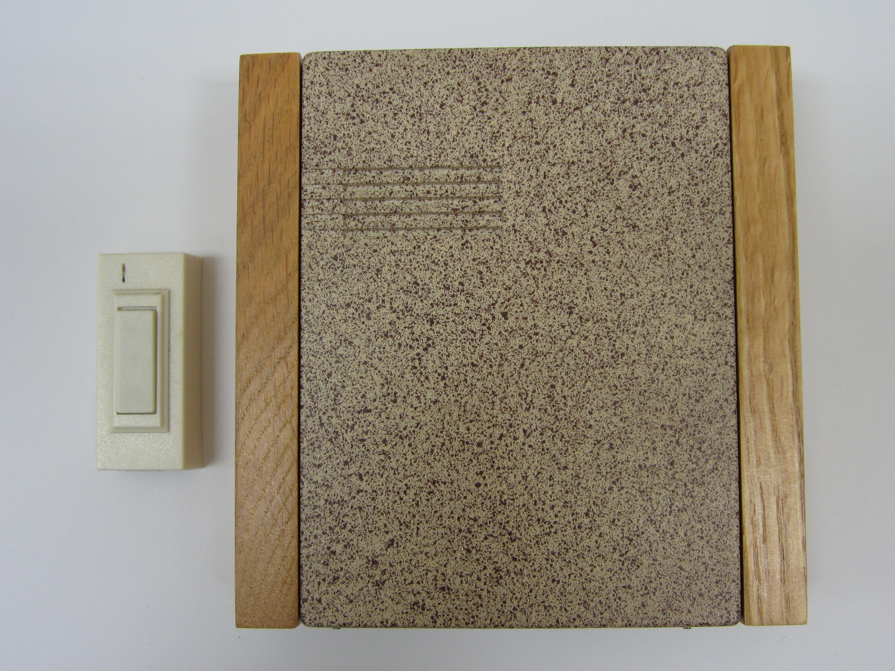
By replacing the doorbell’s original speaker with a recording module, the wireless doorbell is able to play custom ringtones.
Here is a video summarizing the project.
Simple modifications to standard wireless doorbell that will let them play custom ringtones.
By replacing the doorbell’s original speaker with a recording module, the wireless doorbell is able to play custom ringtones.
Here is a video summarizing the project.
Most doorbells just make a simple generic tone. But I thought that it would be fun to modify a doorbell so that it has a customizable ringtone. That way you can set it to play music or custom greetings. You could make it scream on Halloween and play carols at Christmas.
So in this project, I am going to share with you how to add a simple recording module to a wireless doorbell.
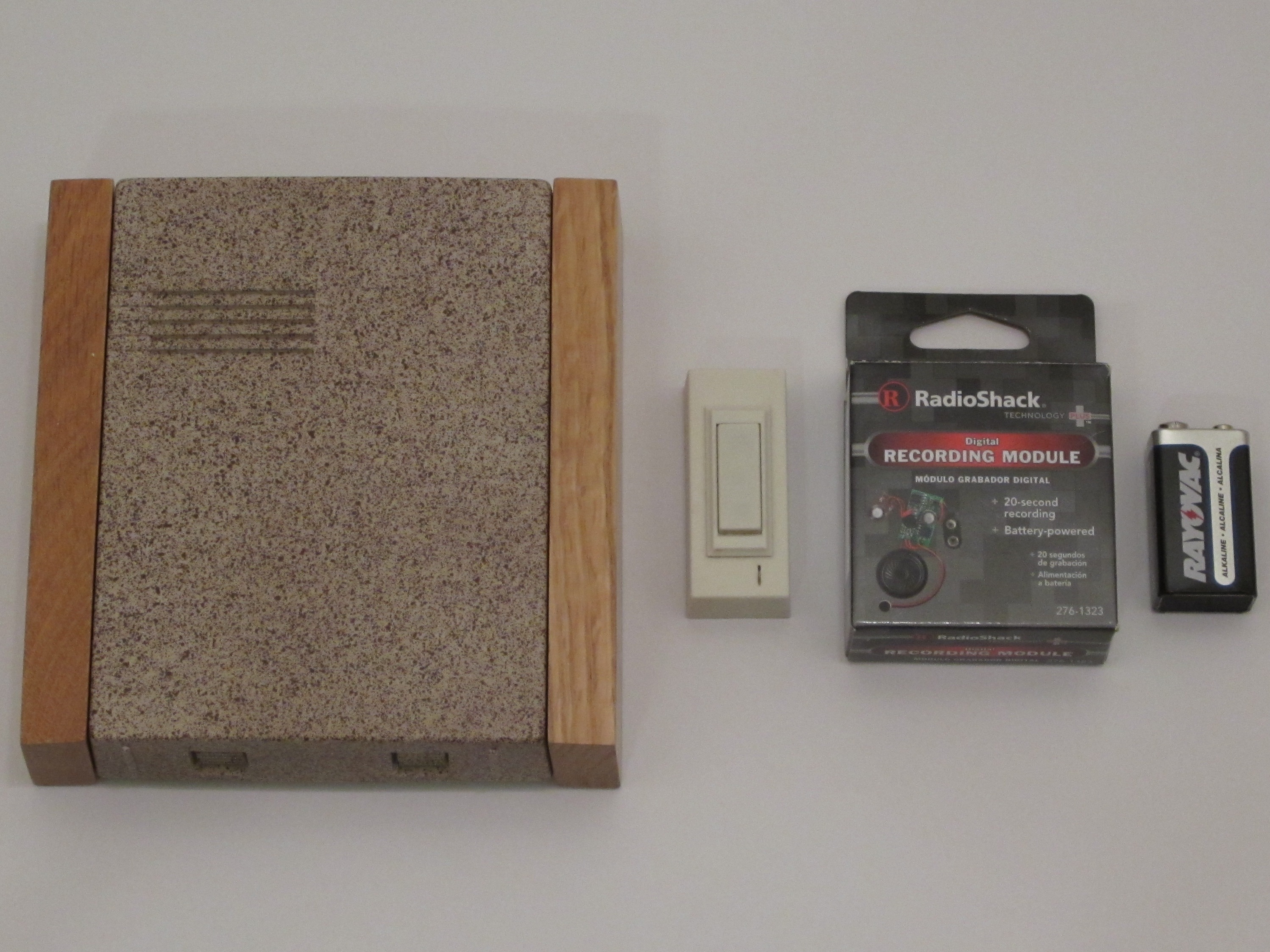
Materials: Wireless Doorbell (and required batteries), 9V recording module (RadioShack Model: 276-1323), 9 volt battery
Tools: Wire strippers, Wire Cutters, Soldering Iron and Solder (optional), Hot glue and hot glue gun (optional)
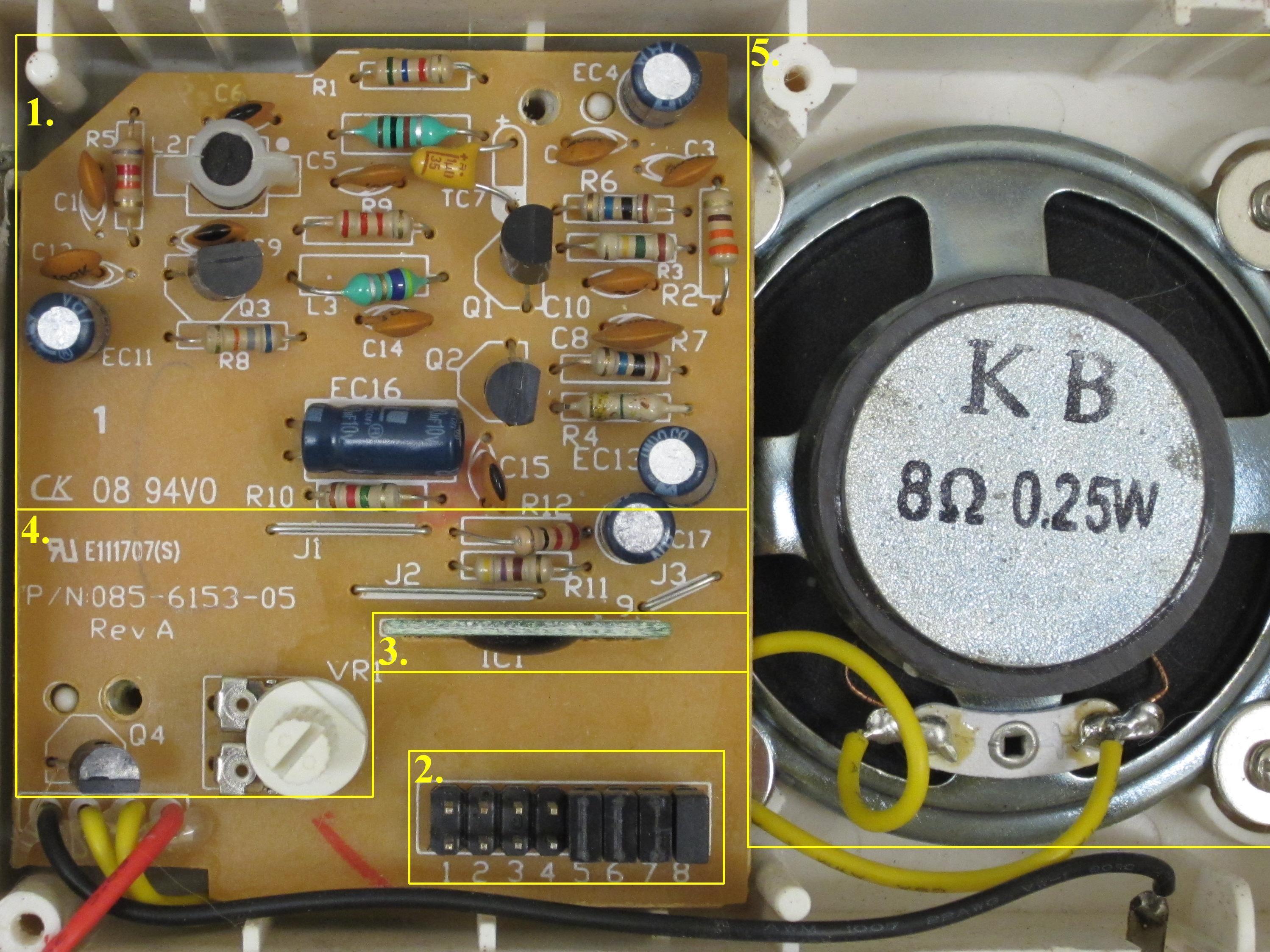
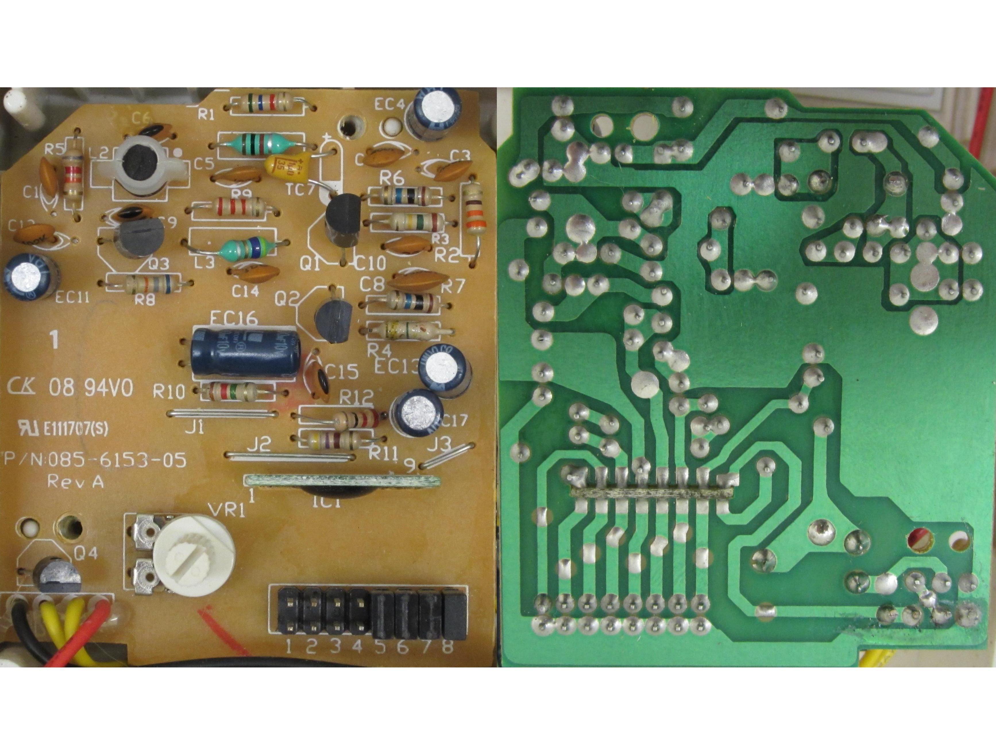
The circuit of the wireless receiver is divided into five main parts.
1. The Radio Receiver: This section filters and amplifies the incoming radio signal.
2. The Decoder Array: This array of jumpers is used to set either the device’s tuning frequency or the security code on the IC chip. This helps to prevent it from interfering with other nearby wireless devices.
3. The IC Chip: The IC chip monitors the incoming signal and detects when the button on the transmitter has been pressed. When the signal is detected, it sends a tone to the speaker.
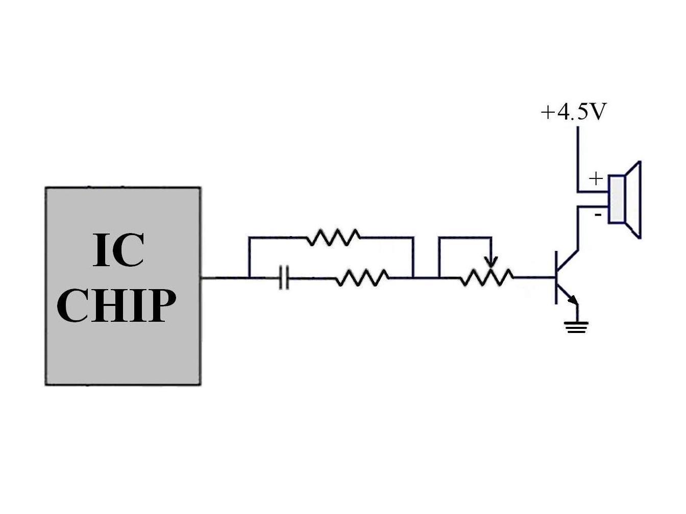
4. The Volume Control: This is a simple transistor amplifier that uses a variable resistor to set the speaker volume.
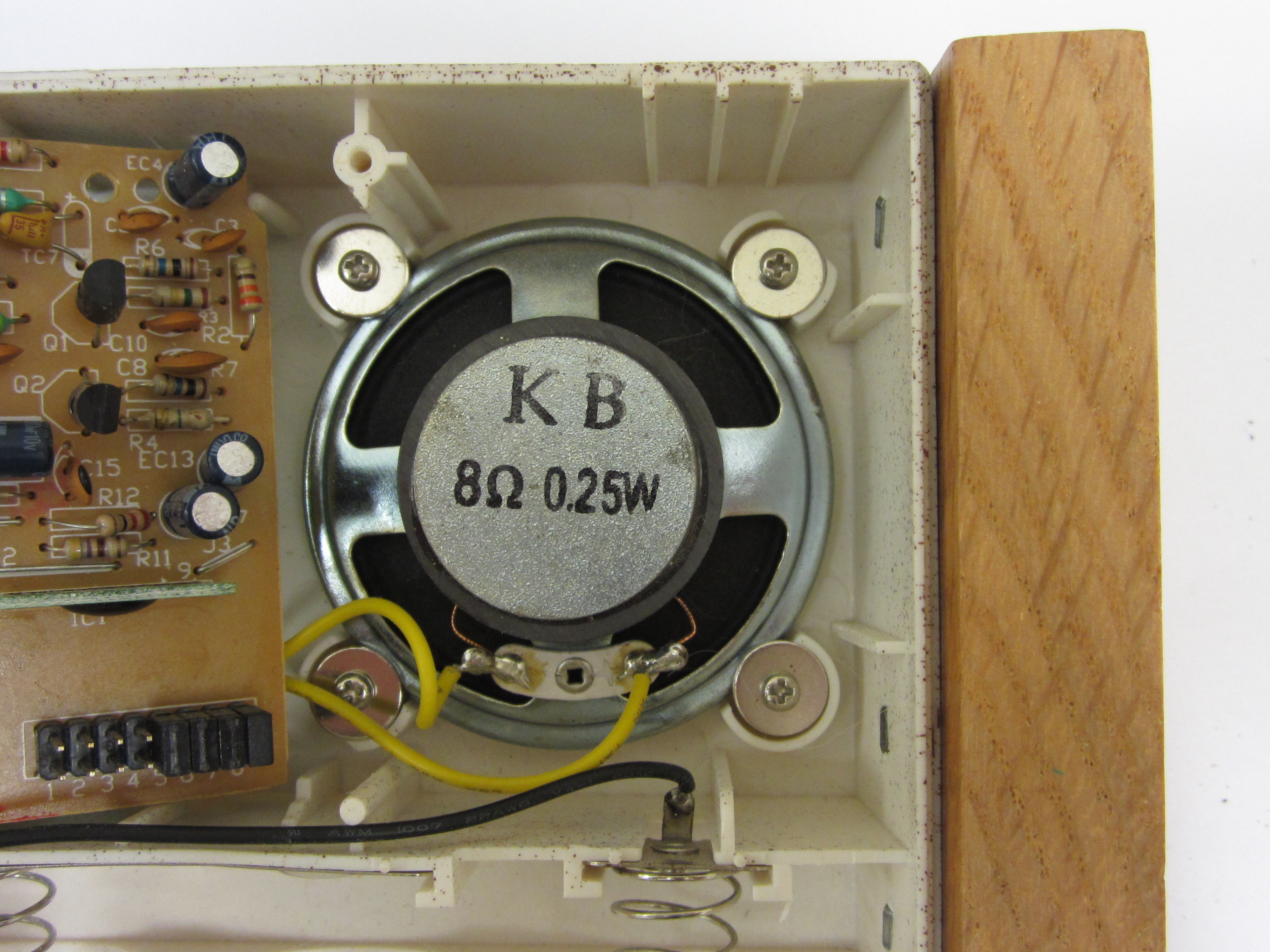
5. The Speaker: The speaker is a plain 0.25W speaker. It is wired between the positive supply voltage and the volume control transistor.
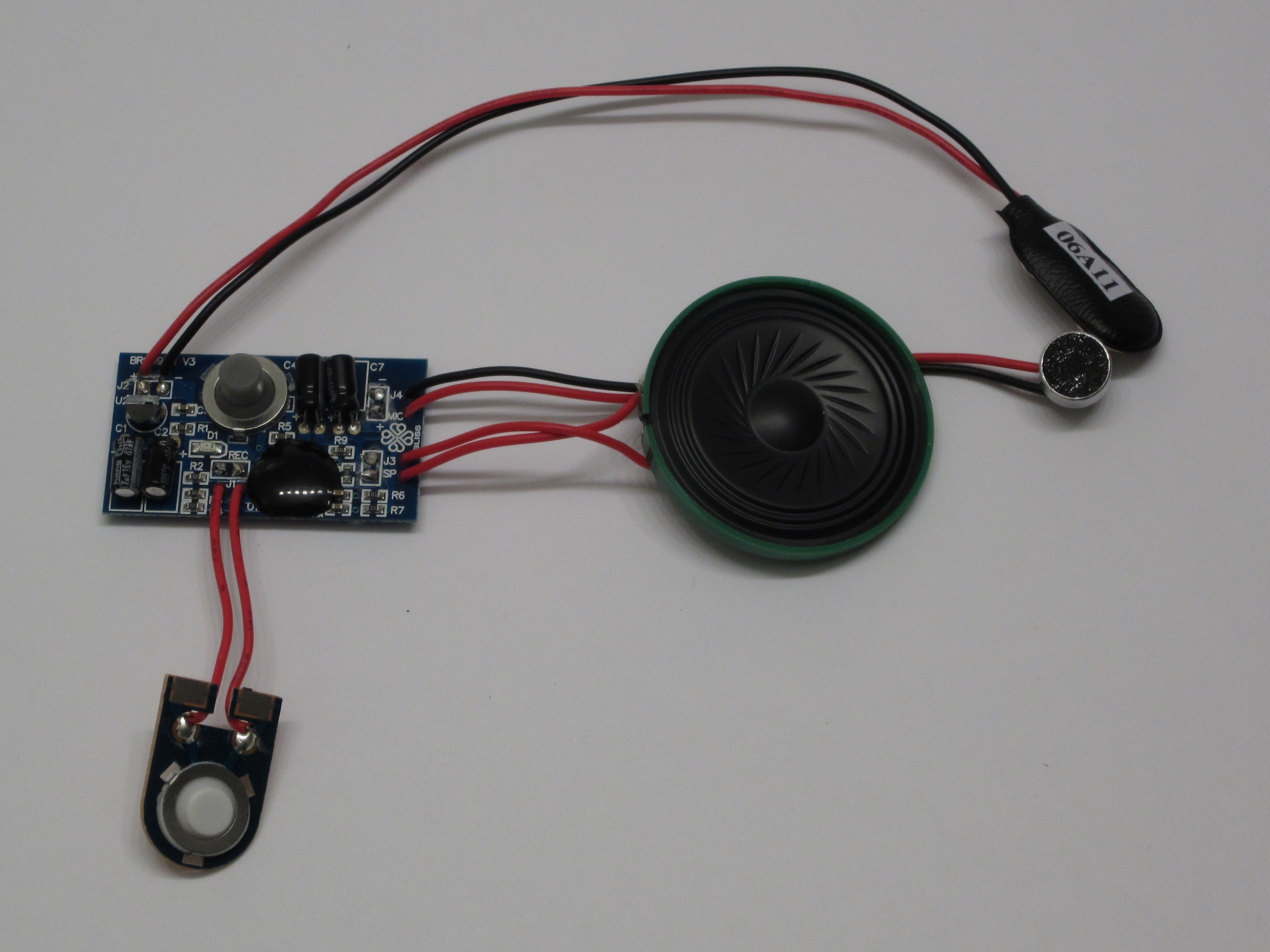

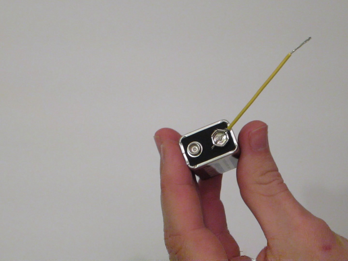
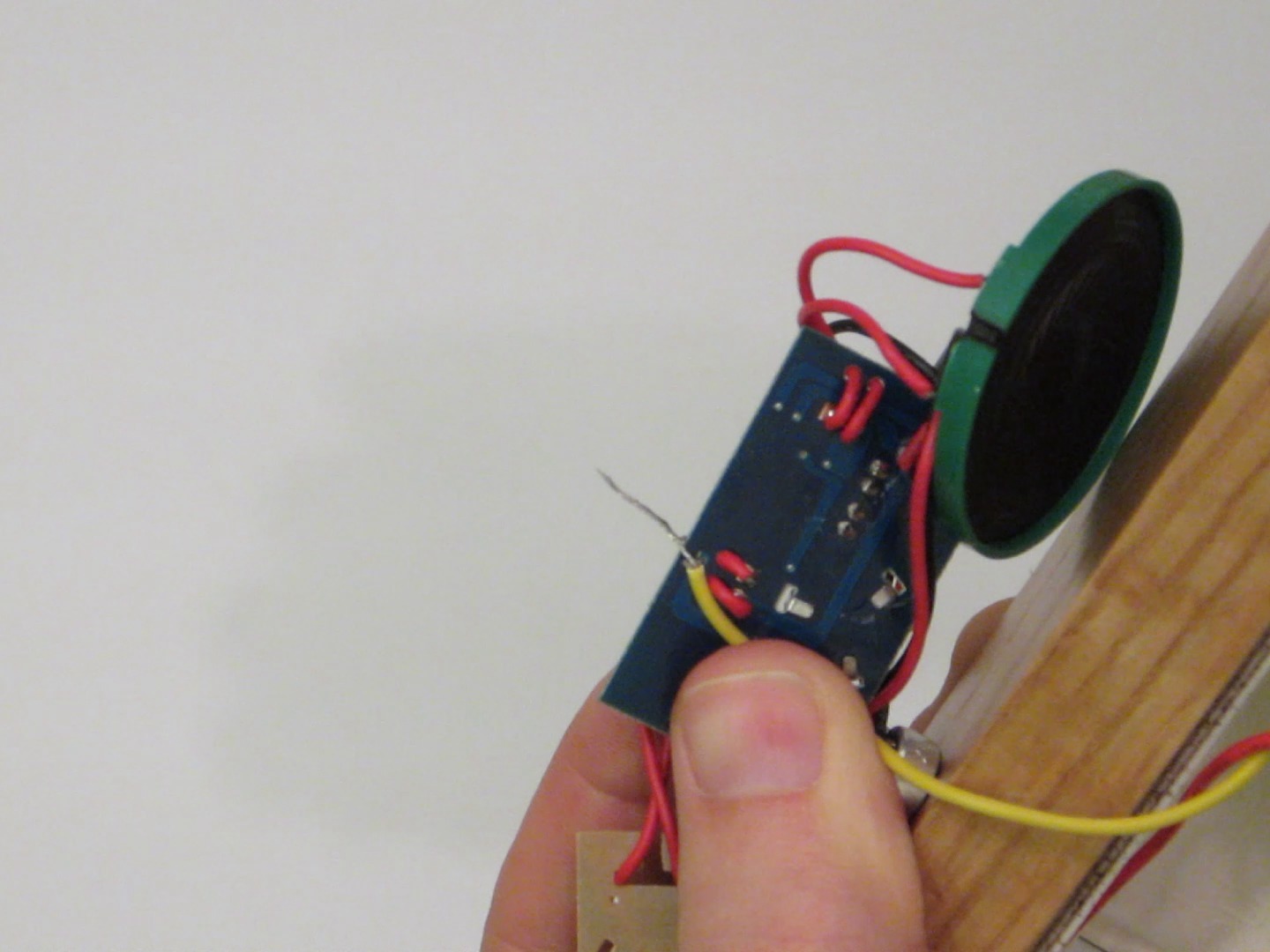
This recording module can store sound clips up to 20 seconds long.
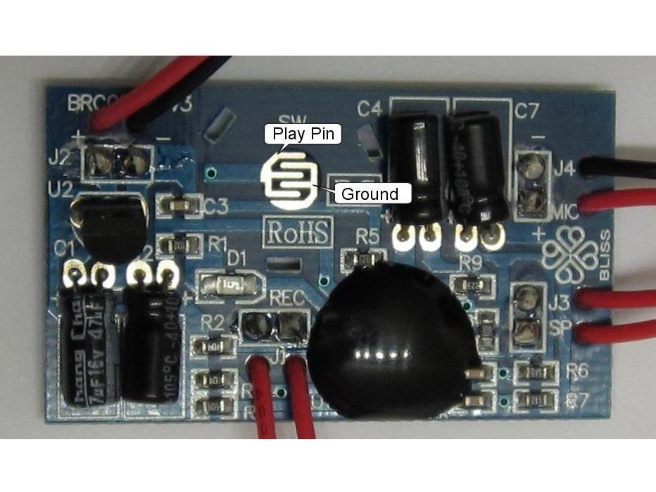
The Play function is activated when the “play” pin on the chip is set to the logical LOW state (in this case less than 4 volts). This is normally accomplished by pressing the Play button which connects the pin to ground (0 volts). It can also be done with an external switch.
A close inspection of the circuit board reveals that there are two open pinholes that are also connected to the “play” pin. By attaching one wire to ground and one wire to either of these pinholes, you can use a secondary circuit or switch to activate the recording module.
In this project we will be using the output of the wireless receiver as the switch to initiate the Play function.
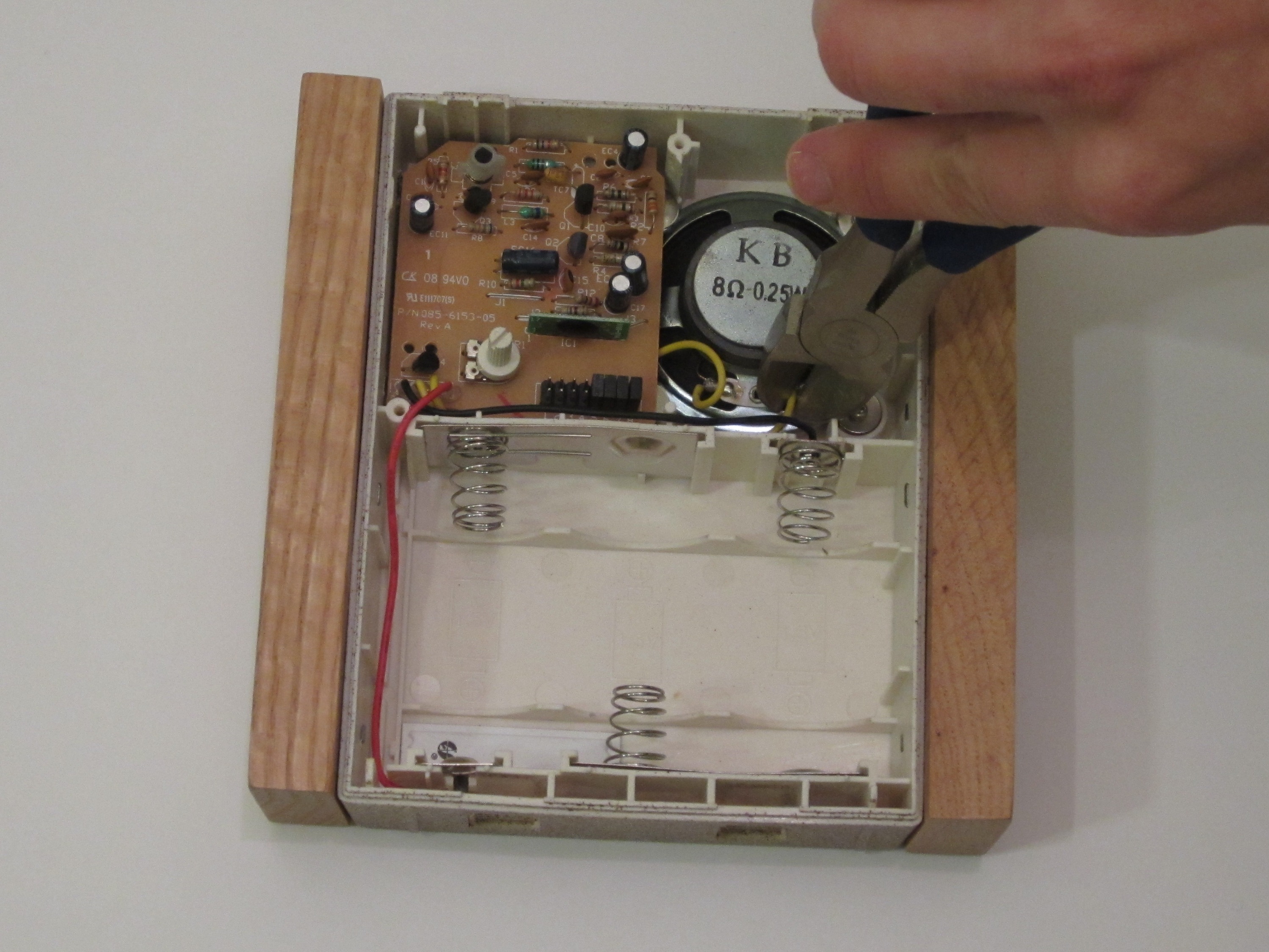
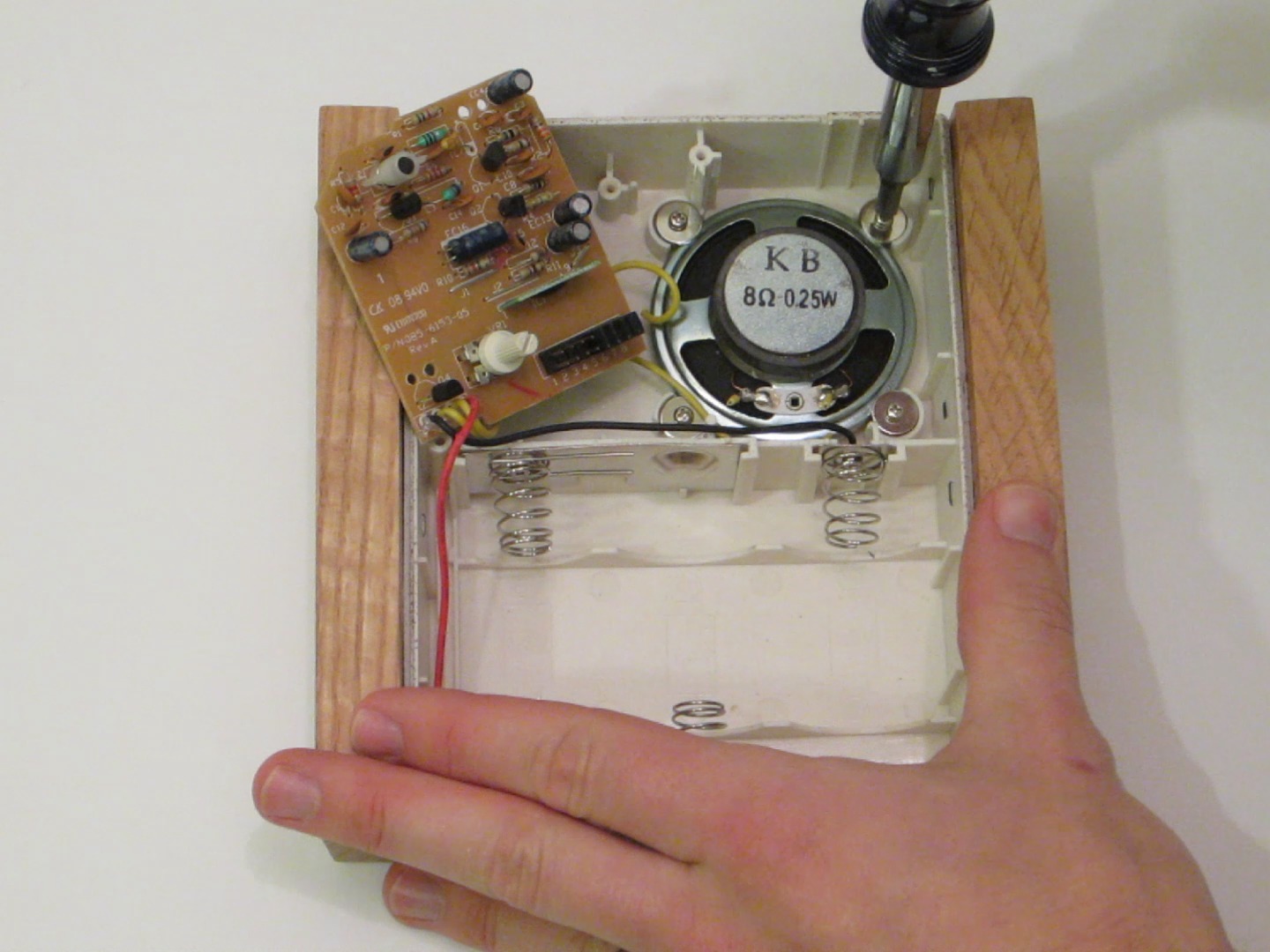
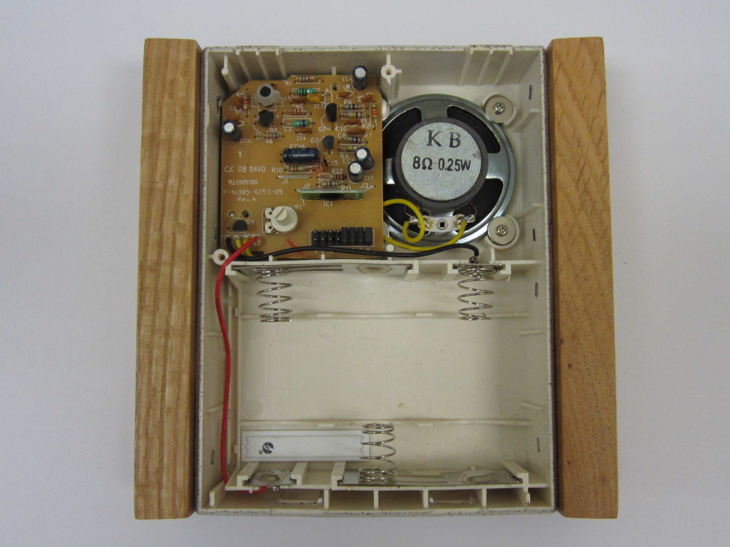
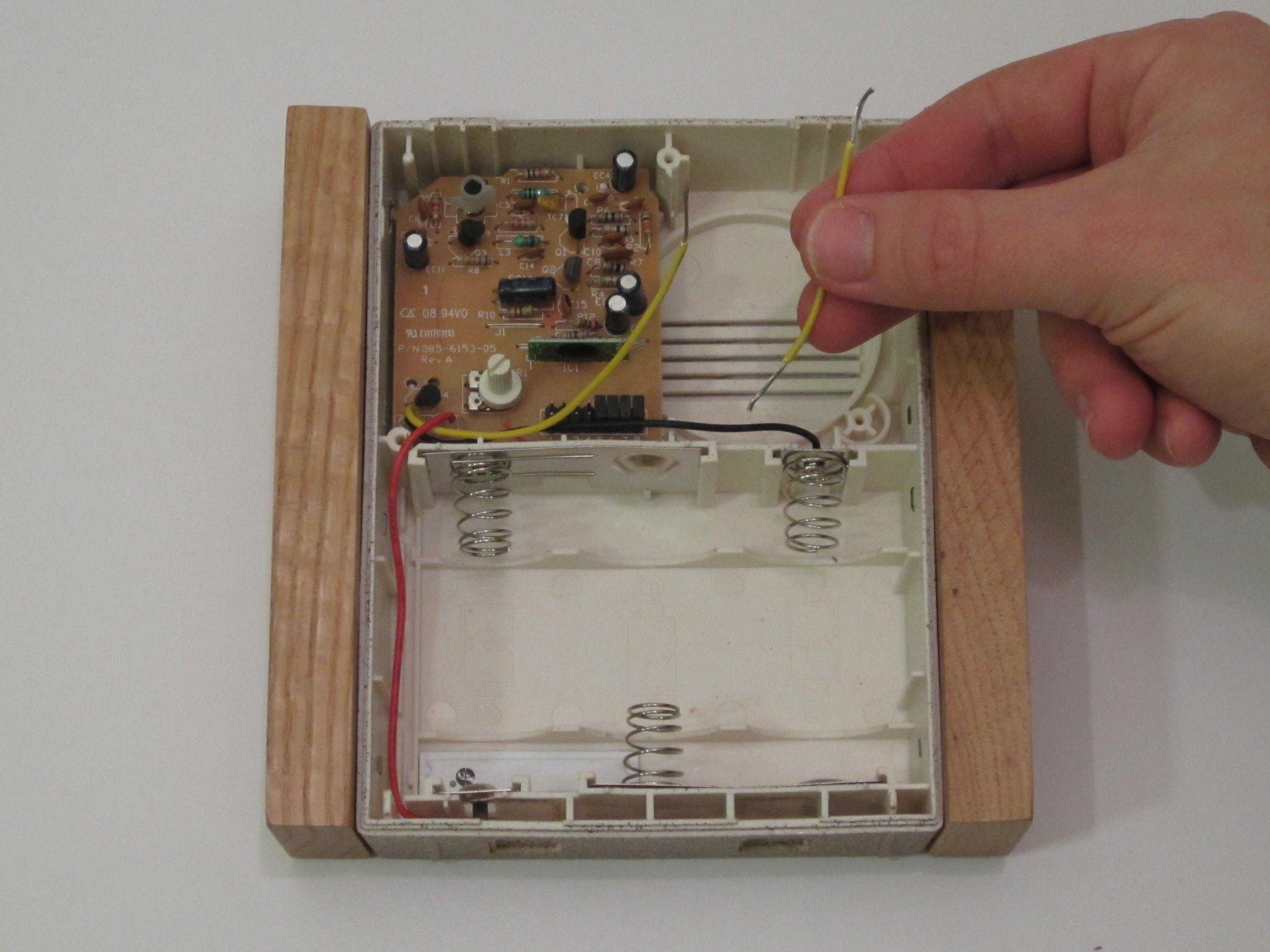
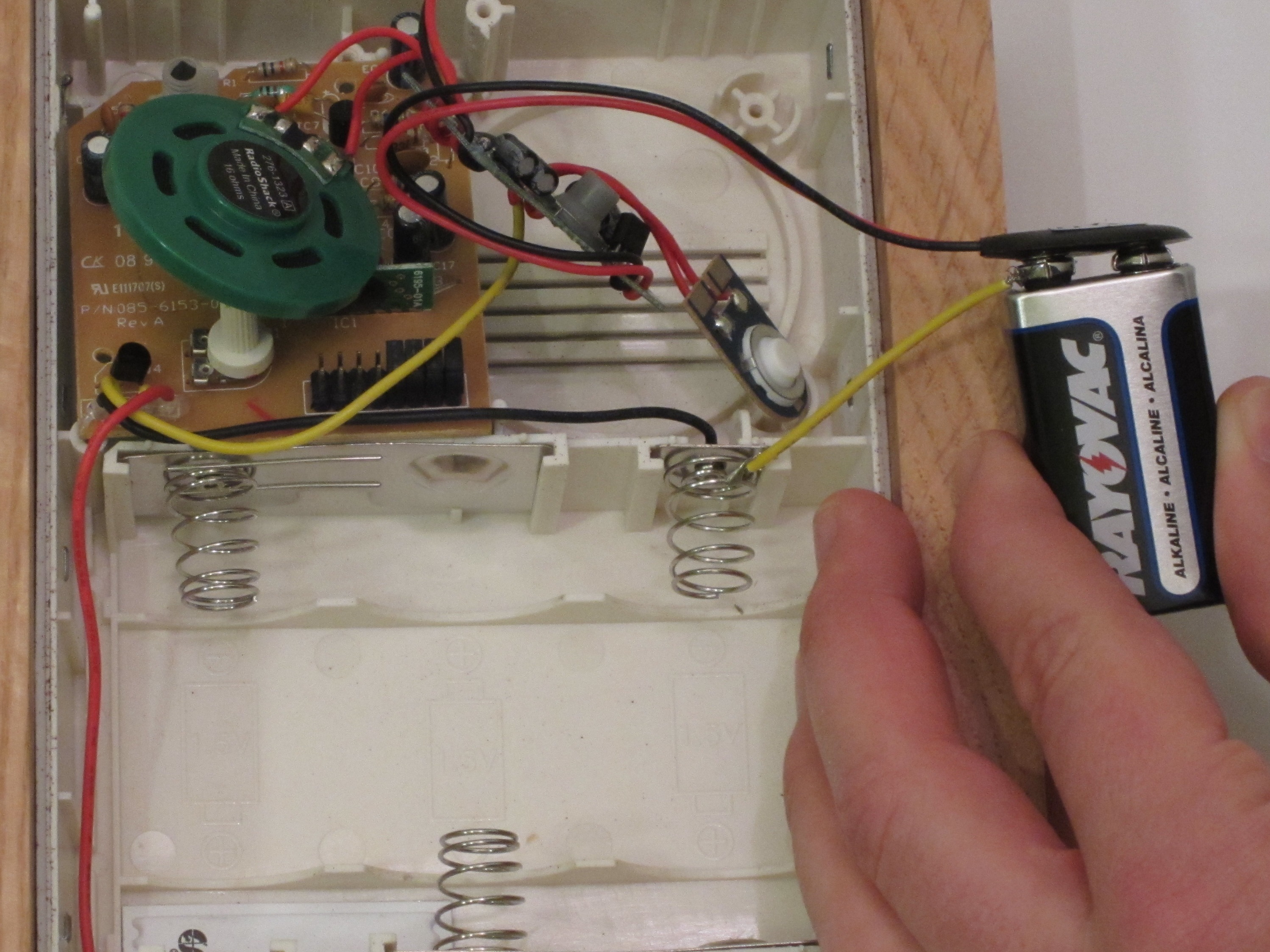
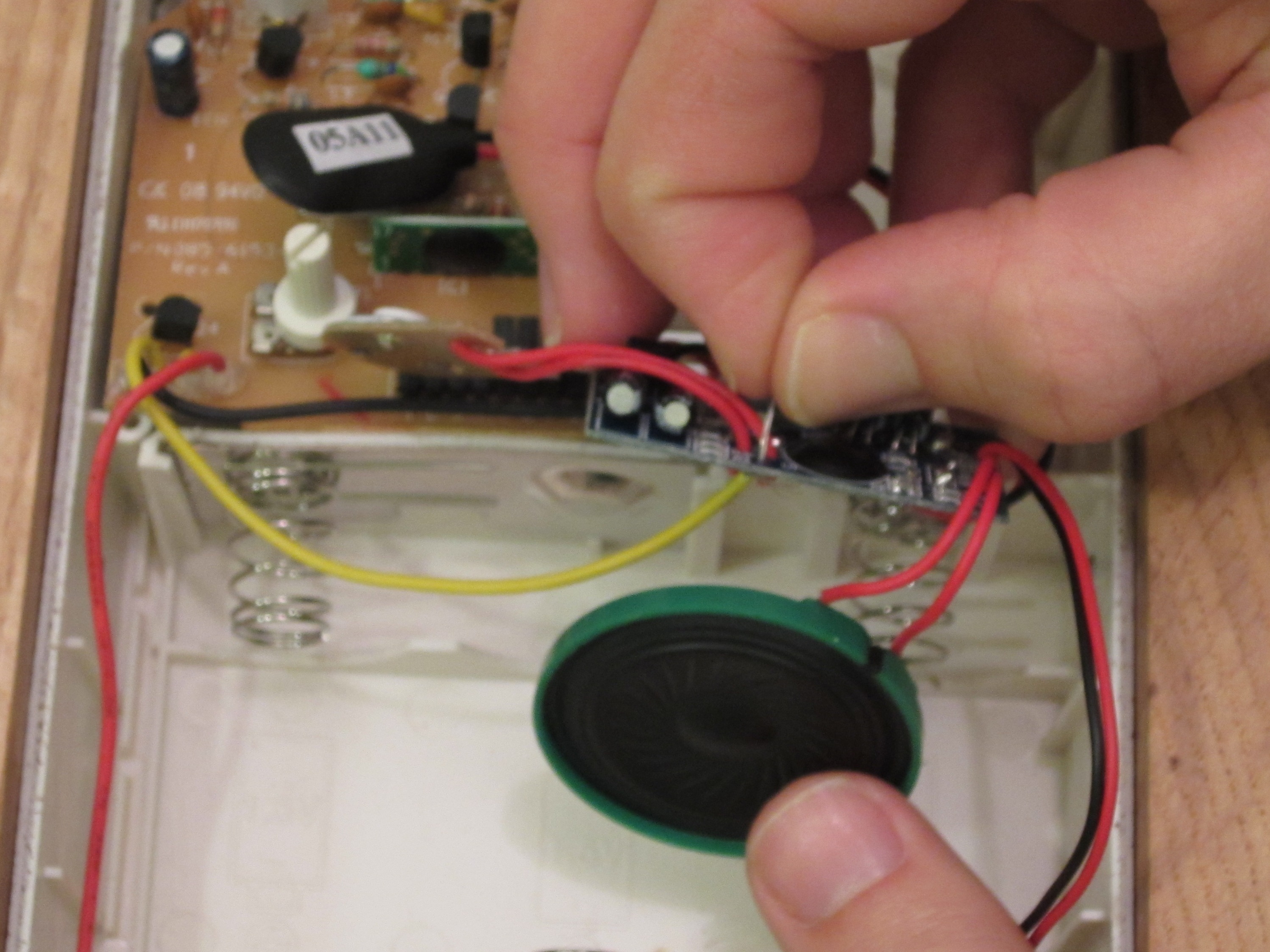
The first step is to remove the original speaker. It will be replaced by the recording module which has its own speaker. Begin by removing any covers on the receiver so that the circuit board and the speaker are visible. Disconnect the speaker from the board by cutting the wires at the speaker terminals.
Remove any screws or fasteners that may be holding the speaker in place. Then remove the speaker from the housing. The speaker may be held in place by glue. If it does not peel away easily, you may need to use a sharp knife to carefully cut the speaker free.
The only parts on the receiver that we will be modifying are the wires that went to the original speaker. First we need to determine the polarity of the speaker. Most speakers have their positive and negative terminals labeled. But if they are not labeled, you will need to determine this by examining how they are hooked up to the circuit board.
In my receiver, one speaker wire is connected to the positive supply voltage (the red wire). I am calling this the positive speaker wire. The other speaker wire is connected to the volume control transistor. I am calling this the negative speaker wire.
Cut the positive speaker wire as close to the circuit board as possible. This leaves you with a loose piece of wire. Strip at least 1/2" of insulation off both ends. On the negative wire, strip off at least 1/2" of insulation from the free end.
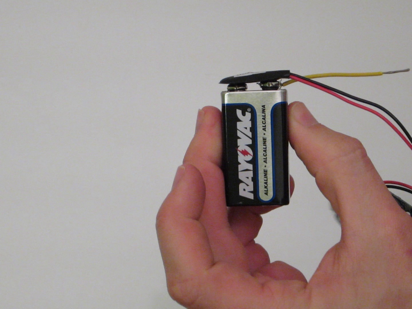
The positive speaker wire that we just separated is used to connect the negative terminal of the receiver battery pack to the negative terminal of the recording module battery. Take one end of the positive wire and insert it into the negative terminal of the 9 volt battery. Then attach the 9 volt battery connector for the recording module.
This should pinch the wire and hold it in place. Then take the other end of the wire and wrap it tightly around the negative terminal of the receiver battery pack. Once you have everything mounted, the wires should stay in place. But if you want everything to be extra secure, you can tape them in place.
I do not recommend trying to solder wires to a battery terminal.
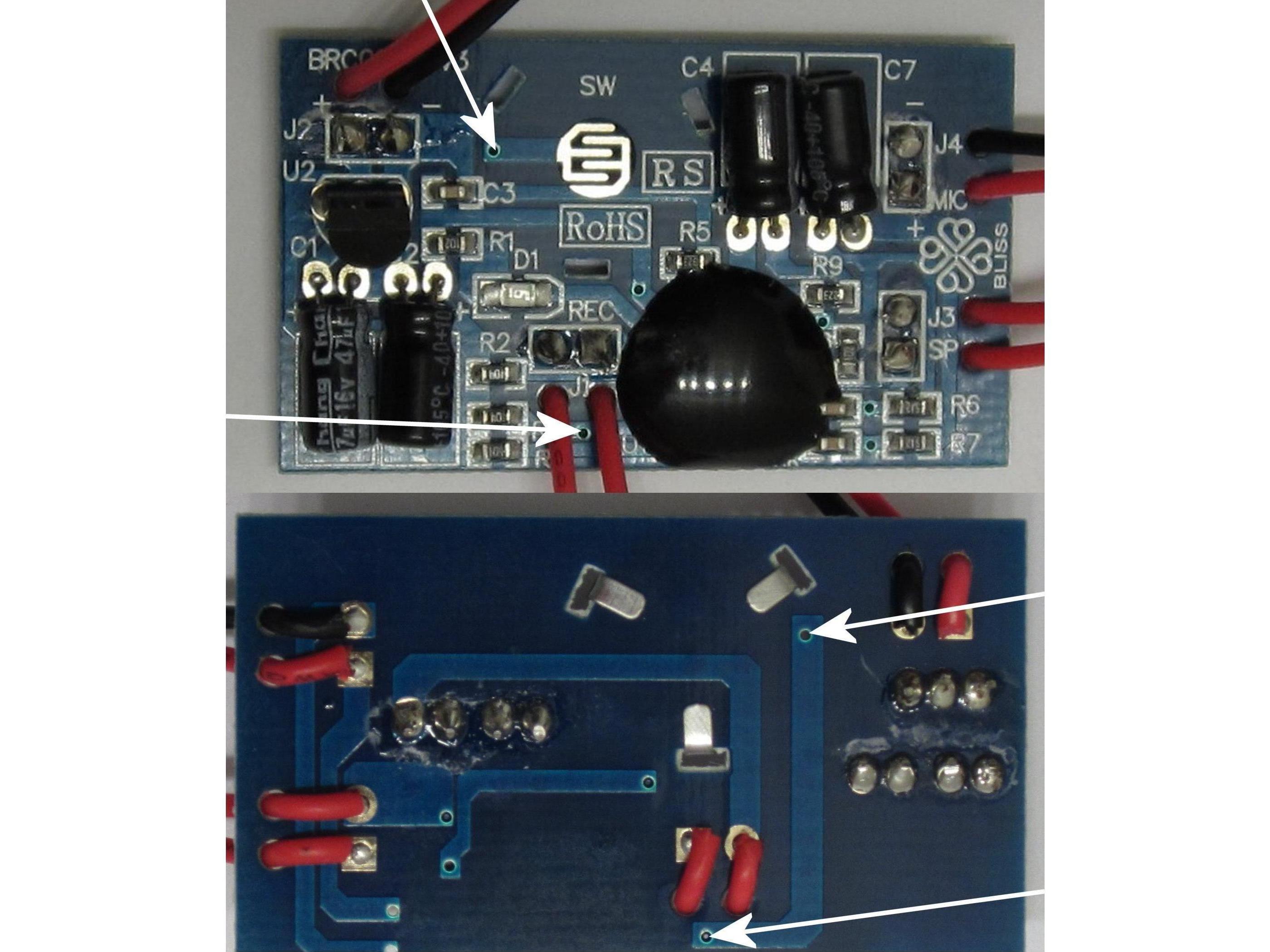
The negative speaker wire will be used to connect the receiver output transistor to the “play” pin on the recording module. One end of the wire is already connected to the output transistor. So we just need to connect the free end to one of the play pin holes that were mentioned in Step 2. You don’t need to solder the wire to the recording module.
You can make a good connection by just twisting the wires together around the board. To do this, Insert a few strands of the wire through one of the holes (the hole is probably too small to fit the whole wire). Then twist the strands of wire back together. As long as wires are tight, it should make a good connection and stay in place.
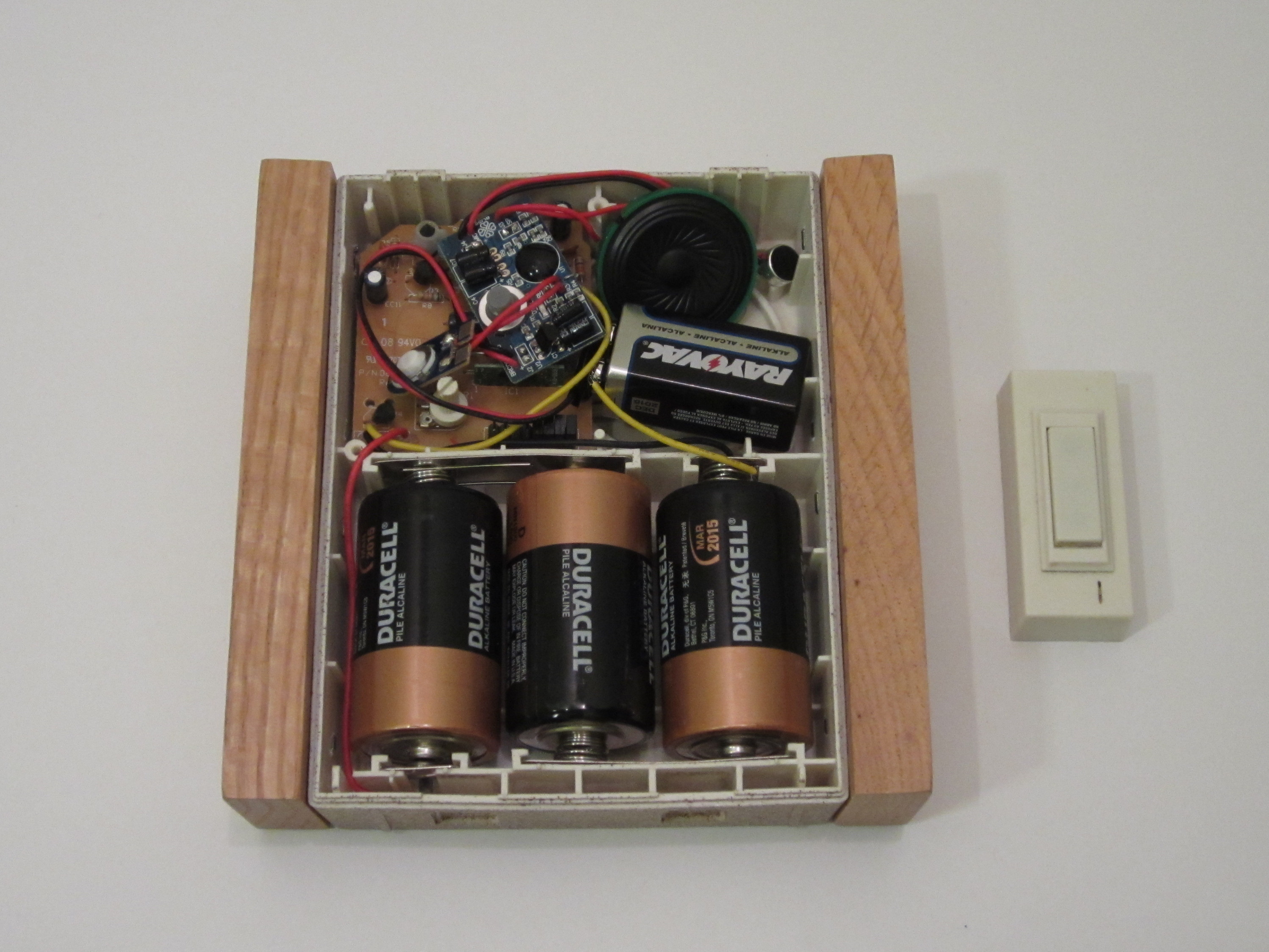
Then just insert all the parts into the housing and your customizable doorbell is complete. If you don’t want the parts to be loose, you can fix them in place with hot glue or some other adhesive. To set the ringtone, just hold the microphone up to your computer speakers and press the Record button as you play a sound file that you want to use.
Then, whenever someone presses the button on the transmitter, the doorbell will play your custom ringtone.
Design Notes: The recording module that I used was not as loud as the original tone. So if you want to make it louder you can replace the speaker on the recording module or use it as the input to powered computer speakers.
Since the Play button also functions as a Stop button, the playback will be interrupted if someone presses the doorbell multiple times before the tone is finished. You can fix this by adding a capacitor between the recording module’s ground and Play pin. This will also help prevent stuttered playback that may happen with some wireless doorbells.


