Angela demonstrates her vivid color-changing shoes and bracelet with this long exposure shot by Geoff Decker of Hidden Vision Photography

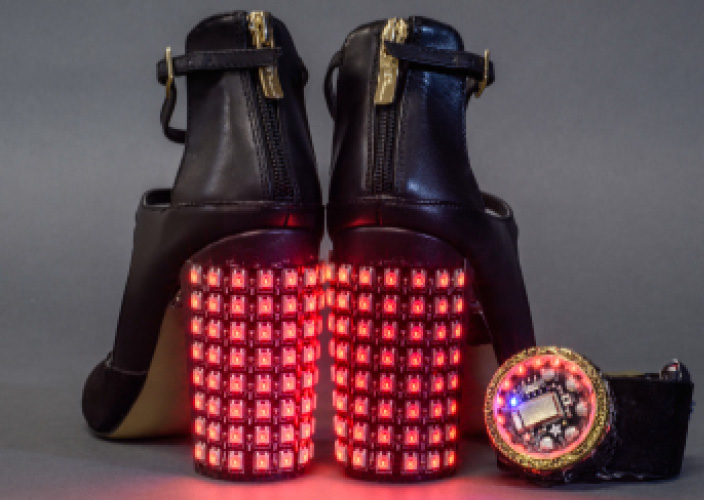
I’m one of those people who is always late to a party because I can’t decide what to wear. I’m also someone who creates elaborate last-minute projects for those parties. This project — I call them my Insta-Hue Heels — was designed and created in less than a week for me to wear to the SparkFun Electronics holiday party.

LEDs on the heels are wirelessly controlled by a matching bracelet connected to Adafruit’s free Bluefruit LE Connect app, allowing for quick color changes for any occasion. The magical effect of instantly controlling color through a smartphone is a great way to interact with other partygoers — let them try changing your look!

It’s easy to replicate with a little time, patience, and the perfect pair of pumps.

Project Steps

1. CODE AND FUNCTION OVERVIEW

Setting up the Bluetooth connection was easy using Adafruit’s tutorials. I started with the framework from their Controller example for the Bluefruit LE board. The bracelet uses the Color Picker tool built into Adafruit’s Bluefruit LE app to control the LEDs. Since the app (for Android or iOS) will only pair to one Bluetooth device at a time, I used inexpensive, short-range RFM69 transceivers to broadcast the color info wirelessly from the bracelet to both heels. This allows control of multiple costume pieces at a time without writing a ton of custom software. I used SparkFun’s well-documented RFM69 hookup guide for code examples to integrate the additional radio broadcasting function into the project.

Upon startup, the Flora Bluefruit module in the bracelet waits to connect to the Bluefruit app. After pairing, opening the app’s Controller menu and the Color Picker function brings up a color wheel for choosing a color on the phone’s screen. Hitting the Send button sends the color values (RGB) over Bluetooth to the bracelet.

The bracelet stores the received values in variables, then retransmits the received color to the heels via the RFM69 radio transceiver. It also displays the color on the bracelet’s NeoPixel ring using Adafruit’s NeoPixel library.

The heels receive the broadcast values and update the color displayed on the flexible LED panels with the ColorWipe() function from the NeoPixel library. Depending on manufacturer of your panels, you may need to adjust the settings in code to set the origin pixel of the matrix.

More detail on the code and my latest prototype is available for download at github.com/GellaCraft/InstaHueHeels.

2. CHOOSING SHOES

Careful selection of the shoes made it easy to integrate and hide the electronics. I found 3″ block heels that nicely accommodate the flexible LED matrix panels. This height also allows placement of a 1,200mAh LiPo battery on the inside edge with enough clearance to avoid potential damage from walking.

3. ATTACHING LED PANELS

First, I carefully wrapped each LED panel around the back of the heel to test fit. To reduce bulk, I replaced the pre-soldered connector with silicone stranded wire. To disguise my wiring against the heel, I used black wires, marked with color-coded heat-shrink at the ends to keep track of them.

I used E6000 adhesive to attach the panels to the back of each heel with the wires running to the top corner of the panel near the inside of the arch. To hold the panels in place, I used small clamps and let the adhesive cure for 24 hours .

4. HARDWARE IN HEELS

I chose to control each LED panel with a Qduino Mini because of its built-in power switch, micro-USB connector, and LiPo battery charging circuit — this minimizes the amount of hardware connections and space needed.

The Qduino nests nicely in the arch of the shoe, with the switch and USB port facing to the side, so you can easily access the switch to turn the project on.

To test the RFM69 transceiver, I first prototyped the circuit on a breadboard. After adjusting the code and confirming functionality, I soldered all the necessary connections and glued the parts under the arch of the shoe. I ran the antenna of the RFM69 down the instep, bending as needed to avoid running underneath the toe and being stepped on.

See the full circuit diagram.

After testing the project, I covered the hardware and battery with gaffer’s tape for some light protection from dirt and wear. So far the shoes have held up after a few nights out, but for long-term durability, I’ll be prototyping a cover to fit over the electronics, probably 3D printed. Gaffer’s tape was also used along the edges of the panels to disguise the seams and keep dirt from building up beneath them.

5. PLANNING THE BRACELET

The bracelet was the most fun and challenging part of this build. After prototyping on a breadboard, I set out to make a compact wearable controller built into a watch-like module on my wrist.

To save on space, I used a Pro Micro instead of a Qduino and moved the battery connection to the band of the bracelet. For Bluetooth functionality, I chose the Flora Bluefruit LE module because its round shape nests nicely within a 16-LED NeoPixel ring. This creates a watch-like face for the bracelet and has a “statement piece” feel. An RFM69 transceiver broadcasts to the heels, and I included a 3-way navigation switch for an easy way to choose modes in future iterations. See the full wiring diagram.

6. BUILDING THE BRACELET

I prototyped and laser-cut an acrylic casing for all the electronics (except the battery). A gold pendant found at a craft store created a cover for the casing .

The first hardware layer houses the NeoPixel ring and Flora Bluefruit. The middle holds the navigation switch and an acrylic spacer with an open center to accommodate the wiring from the bottom layer. The base houses the RFM69 stacked on the Pro Micro, with engraved channels for wiring and the RFM69’s antenna.

A piece of electrical tape over the Pro Micro protects it from any shifting that may occur with the RFM69 board above it.

Soldering everything together to fit was a bit of a puzzle, and cutting the wires as precisely as possible to reduce bulk inside the casing was a fun challenge.

Once I had it all assembled, the layers were reinforced with hot glue to avoid shifting during wear.

7. FINISHING TOUCHES

To create a bracelet, the module is attached to black velvet ribbon with gold magnetic clasps.

I also glued a piece of clear acrylic inside the gold ring to protect the hardware, and I painted the white plastic of the LEDs black to minimize the contrast.

Finally, the battery powering the project is attached to a LilyPad Simple Power board near the clasp and tucked into a pocket under the band .

NEXT LEVEL KICKS

The first version of the Insta-Hue Heels uses a color wipe to update the color of the LED matrix from top to bottom. Even this simple animation is a crowd pleaser!

With a little extra programming, you can set your matrices to display complex animations and modes, chosen with a menu on the bracelet controlled by the navigation switch. I plan on adding some sparkling patterns, mirrored animations across the left and right heels, and other fun display options.

You can find updates to the functionality and code on my website along with more build photos and video demonstrations.

I’d love to see what you’ll do with
these heels!

Further resources

[+] Code and templates available at Github

[+] See more behind-the-scenes build photos

[+] SparkFun RFM69 hookup guide

[+] Adafruit Flora Bluefruit LE guide

[+] Adafruit Bluefruit LE Connect guide: