








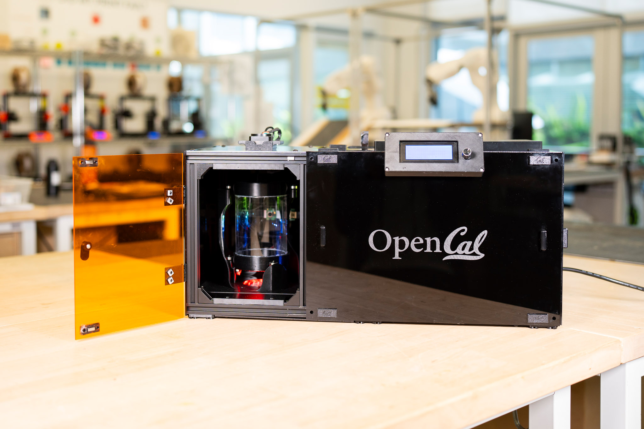


Computed axial lithography, or CAL, looks different from other forms of 3D printing. A vial of resin rotates while a sequence of carefully computed images are projected through the volume. Where enough light accumulates, a part forms — all at once, in just minutes. There are no layers and no support structures. Introduced by our team at UC Berkeley in 2019, the CAL process was covered by Make: in Volume 88, but now we have a new development: a DIY version you can make at home.
The CAL team have condensed much of our lab setup into a new, accessible open-source platform. OpenCAL is a project designed to let the public build, test, and contribute to the volumetric additive manufacturing (VAM) community.
The project covers machine construction, the software needed to fabricate parts, and resources for obtaining the resin. Once you’ve gathered the components and 3D printed the parts, the machine can be assembled in an afternoon.
How CAL Printing Works

The core idea behind OpenCAL remains the same — tomographic reconstruction. It’s like a CT scan in reverse. In a CT scan, X-rays are used to measure a person’s internal structure and then computers reconstruct it volumetrically. In CAL, the process starts with a 3D model. From that model, the software computes the projected images needed to reconstruct the part in resin. The open-source software that drives this is called VAMToolbox. It calculates light dosage so that only the regions meant to form the part receive enough light to solidify, while the rest remains liquid.
As the light passes through the spinning vial, it is effectively delivering a dose of photons to the whole part at once. Because of that, machines like OpenCAL can print much faster than traditional methods, with inch-scale objects forming in mere minutes.
Building Your OpenCAL Printer
OpenCAL was designed to require as little specialized equipment as possible. The build calls for a basic set of hand tools, a 3D printer, and optionally a laser cutter. The frame is made from pre-cut 2020 aluminum extrusion and brackets, the optical system uses a compact DLP laser projector and a Fresnel lens, and the electronics are powered by a Raspberry Pi 5 with a Pi Cam. We designed the project so that the parts can be ordered from common suppliers and delivered quickly, but we also left room for substitutions: many of the components can be swapped for parts already found in a well-equipped shop or makerspace.
- Stepper motor
- 3D-printed rotary stage
- Skateboard bearings
- Glass vial with photoresin
- RGB LED grid provides illumination
- Pi Camera watches prints for completion
- Raspberry Pi inside! USB access on top
- Fresnel lens in 3D-printed shroud
- Display interface, 20×4 LCD with selector knob
- 1080p mini DLP laser projector, off the shelf
- Linear X-Z stage adjusts projector position
- Standard aluminum extrusion, 20mm×20mm
- 24V DC power supply and buck converters

The build itself follows a familiar pattern from other open-source machines. Instead of one complicated assembly, the system is broken into smaller subsystems. Makers work through the frame, optics, and electronics separately, then bring everything together at the end. The design was also intended to introduce users to the core ideas behind the technology and to show which subsystems matter most. In some cases, that means design decisions that may not be obvious at first, such as making the main rotational holder one solid piece to preserve accuracy.
Even so, this will likely feel more like the early days of desktop 3D printing, when the machines were still a hobby and not yet routine tools. Builders will be working with something new, and good results will depend on a range of factors, including precise rotation, optical alignment, and properly generated projections. Early users should probably expect as many failed prints as successful ones. But we believe the maker community will be essential in turning this from an experimental machine into a more common fabrication tool.
Printing and Post Processing
Instead of G-code, the machine uses simple MP4 video files uploaded to the Raspberry Pi. A basic GUI allows users to select print files, adjust speeds, and control other aspects of the hardware. The core software used to generate those projections, VAMToolbox, is also being condensed into a more accessible GUI-based workflow. Users will import an STL, voxelize it (convert the STL to cubes), and then optimize the image sequence that becomes the print video. That is where much of the process happens, and it is also where future updates are expected to improve print quality the most.

We’ve spent a great deal of time incorporating advances from the broader research field into the OpenCAL system, from metrology that helps determine when a print is complete to highly specialized resins. Resins that previously had to be formulated in a lab using exact ratios are expected to become commercially available. Through partnerships with Formlabs, we expect users to be able to buy resin in one-liter quantities for around $100. And yes, after a part is removed from the vial, the resin can be reused.
A wide range of geometries should be possible with this setup, since nearly any shape can, in principle, be fabricated. One of the more interesting features of the process is something the team calls over-printing. Because parts are not built layer by layer, an existing object can be embedded directly in the resin. A projection sequence can then account for that object and build new material around it. A simple example would be embedding a screwdriver bit and then printing a handle around it. The result is something closer to low-volume injection molding than conventional 3D printing. To support this direction, the team has implemented a stepper motor with an encoder and an imaging system that may eventually allow the machine to detect existing objects automatically for over-printing.

Once a print is complete, there are two possible post-print washing paths to get rid of the excess resin. The first option is similar to other resin printing processes such as SLA or DLP: remove the part from the vial with tweezers, then place in an IPA bath for about 40 minutes. The second option uses a centrifugal setup we designed that works a bit like a salad spinner: the vial and printed part are spun rapidly to fling excess resin off both the part and the container.
Then the part is post-cured with extremely bright light to fully solidify it. There are two important differences from traditional resin printing. First, these parts will generally be more undercured, so they need to be handled more carefully. Second, because of how the resin behaves, final curing must take place in a water bath to prevent the surface from remaining sticky.
Help Make the Future
The tools needed to make OpenCAL are maker-scale: an ordinary FFF printer, optionally a laser cutter for acrylic panels, soldering equipment, hex keys, and a crimper. This is not an out-of-the-box solution, but it’s a relatively direct path into a fabrication process that would otherwise remain in academic labs. More importantly, it gives people a chance not just to use the technology, but to improve the machine, refine the print process, and invent entirely new applications for it.
If you’re interested in the OpenCAL project, visit our website opencal-org.readthedocs.io. It includes links to the community Discord, related academic papers, CAD files for printing, and step-by-step documentation for the full workflow.

The team who made this happen are: Erik Dahlhaus Broude, Angel Arambula, Ishani Chowdhury, Maya Lund, Daniel Oslund, Huy Tran, Carl Kruse, Bryan Vu, Evan Percival, Ian Bos, Paul Morenkov, Wangari Mbuthia, Ty Snyder
Photography by OpenCAL unless otherwise stated.
This article appeared in Make: Volume 97.