You may recall the rocket flight that recorded acceleration, rotation and pressure in a model rocket using an iPhone and a TI SensorTag. We got a lot of questions about afterwards. People wanted to know why we didn’t get movies, too.

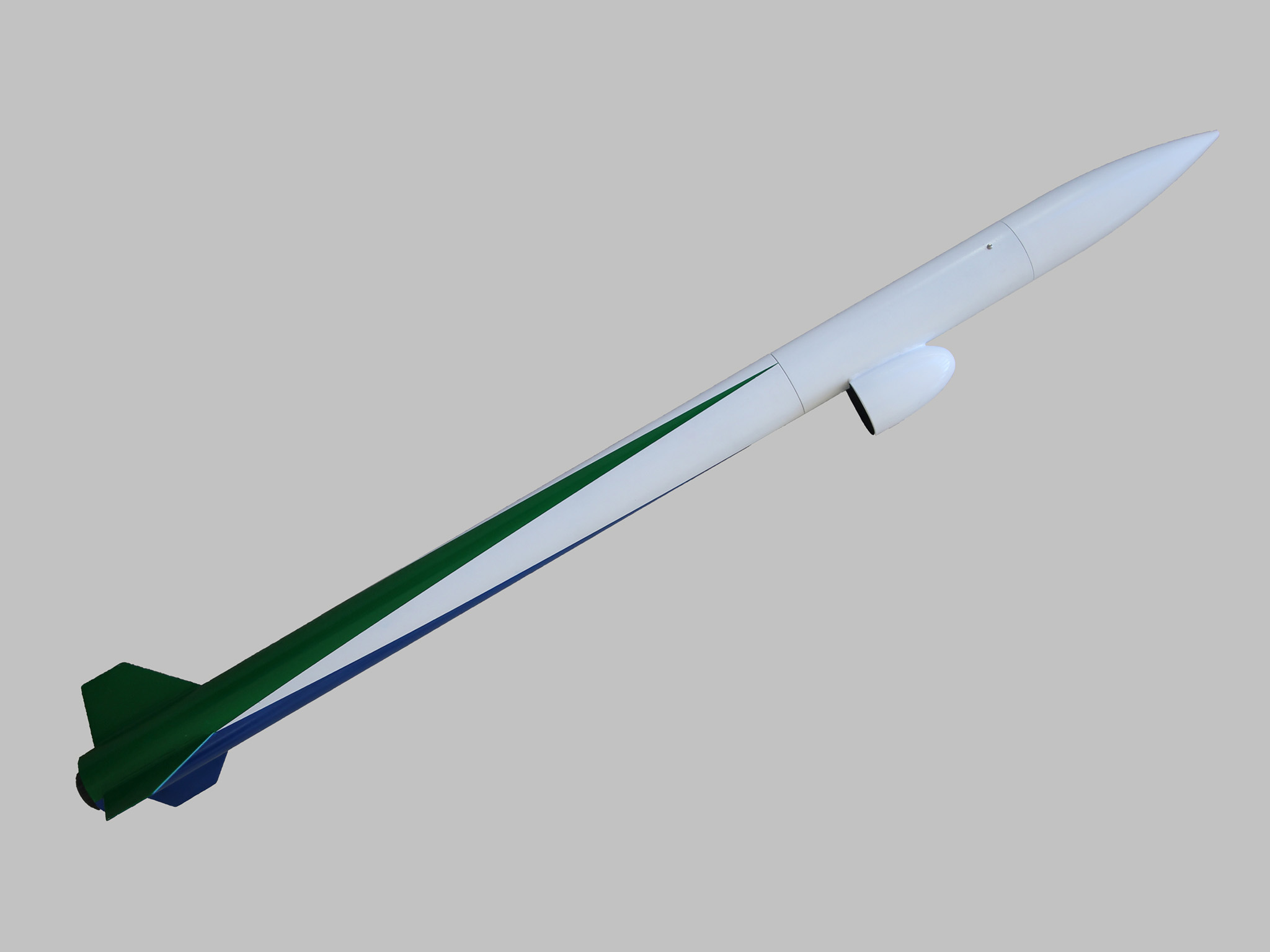
It turns out getting movies from a rocket is pretty simple, but getting good movies from a rocket is a bit more involved. This project shows how to build a payload bay to capture movies pointed down along the length of the body tube.

Project Steps

This is Pixel, the rocket that made the movie from the introduction. It’s built using LOC Precision 2.56″ body tubes and a standard LOC Precision 10″ long payload bay, but the diameter is the same as an Estes BT-80.

This project covers building and installing the camera. Basic rocket construction is covered elsewhere.

All project steps can be replicated for low, mid or high power rockets.

For D or E Estes engines, use an Estes BT-80 body tube and balsa parts rather than plywood. Typical altitudes: D12-3: 150 ft, E9-4 250ft.

For F, G and H engines, use LOC Precision 2.56″ body tubes. This is the version shown. Typical altitudes: F40W: 900 ft, G64W: 1500 ft, H128W: 2300 ft.

I used a retired iPhone 4, but any small movie camera will work. I do recommend using an old, retired phone if possible. Even NASA has an occasional failure!

Build the camera mount from 1/8 inch plywood (balsa for D or E engines). The specifics will vary a bit based on the exact phone you use.

Cut the plywood so it fits snugly in the body tube. The nose code should hold it in place against the bottom of the payload bay. Trim the top, bottom and sides as needed for your particular payload bay. Here you see:

A notch in the bottom to leave room for the top of the eyelet poking through the bulkhead at the bottom of the payload bay.

The lower edges are trimmed a bit because the LOC Precision payload bay uses a tube coupler design that reduces the inside diameter of the payload bay.

The top is trimmed to fit the base of the nose cone.

The camera faces away from the support, so on an iPhone 4, the power button and screen are facing the plywood. Use a scroll saw or jigsaw to cut a rectangle so the screen is visible, and drill a hole so the power button can be pressed through the mount.

Cut notches just above and below the screen for rubber bands. These will hold the iPhone in place. No, it won’t slip–see the next step. :)

Cut a strip from 1/8 inch square bass wood (balsa for D or E engines) to act as a support. This keeps the iPhone from sliding down; the rubber bands will just hold it in place. Add additional support below the main support as shown. Use epoxy to hold these parts in place.

Add side supports from 1/8 inch square bass wood (balsa for D or E engines). These hold the iPhone perfectly vertical so the lens looks out of the camera port we will cut in the body tube, and doesn’t slip to one side. The sides of the strips will need to be beveled with a hobby knife to allow for the curvature of the body tube.

Here’s the finished camera mount with an iPhone attached. Note that the iPhone is upside-down in the rocket. The lens is near the bottom, so the fairing will be lower on the rocket, making it more stable.

The camera position needs to be precisely fixed relative to the camera port. Add 1/8 inch square bass wood rails to form a slot for the camera holder. Use epoxy to hold the rails in place.

The rails stop part way down on the side where the iPhone will be. That’s because the iPhone just barely fits in this tube.

The LOC Precision payload bay uses a tube coupler and bulkhead arrangement, so the inside diameter of the payload bay gets slightly smaller at the location of the tube coupler. That’s where you see the break in the longer support rail. There is a corresponding notch in the camera mount to accommodate the change in diameter.

This rocket uses an old iPhone 4 for the movie camera, but of course, you can use any small video camera. All have different optics, though, so you will need to make careful drawings to get openings, mirror sizes and fairings correct.

Start by making a drawing of the body tube. It is its own circle template!

Form a side view of the rocket by extending parallel lines form the sides of the circle.

Draw the 1/8 inch plywood (or balsa for D or E engines) camera support in the center of both the top and side views.

Draw the iPhone or other camera, and mark the exact location of the camera lens.

Prop the iPhone some known distance over a ruler and look to see the side and top distance the camera can see. Do this while taking a movie, not a photo–the sizes are different.

Use this distance to mark the view angle on both the top and side view drawings. That’s the triangles you see in the drawing.

Transfer the location where the camera view hits the body tube to the body tube. It should be a rectangle. This is the camera port. Cut the port using a hobby knife.

Slide the iPone into the tube. Make a movie to double-check the camera port to make sure it is big enough–and hopefully in the right place!

The mirror will be at a 45 degree angle to the iPhone, reflecting the image so the movie points directly down the body of the rocket. Build a mirror guide from three scrap pieces of balsa, one for a base that will sit on the iPhone, and two vertical pieces that get trimmed to exactly 45 degrees.

Place the mirror guide directly on the iPhone, which is mounted on the camera mount inside the payload bay.

The lowest edge of the guide should be closest to the nose cone, and the 45 degree cut should just touch the body tube.

Cut a piece of thin scrap balsa about 2 inches square. This will be used to determine the size of the mirror. You can get the approximate size from the original drawing made to determine the size fo the camera port.

Use a piece of coarse sandpaper wrapped around the body tube to sand the piece to conform to the body tube when it is held at a 45 degree angle.

Tack the mirror substitute in place with a couple of drops of CA glue.

Remove the mirror guide by sliding the iPhone out of the payload bay. The mirror guide will drop into the payload bay, and can be shaken out of the top.

Taking movies constantly to check for clearance, cut two side supports from 1/4 inch plywood (balsa for D or E engines) and sand them to fit in place.

These slant significantly to the side, since the camera view is expanding quickly. See your drawing from step 7 to get the initial angles.

Trim the balsa piece that is substituting for the mirror so the camera just barely sees past the end of the piece. Extend it with tape if needed.

Trim the sides to match the sides of the plywood supports.

Remove the balsa piece. This is your mirror template.

Place tape over the back side of a mirror blank. This can be a thin mirror from a hobby store or a small mirror salvaged from an old makeup case. (My wife is very tolerant. You may recall she let me fly her iPhone in an earlier rocket. You’ll have to find your own tolerant spouse–mine is taken.)

Leave the tape in place, even after the mirror is permanently installed on the rocket. It reduces the chance of breaking during grinding, helps protect the mirrored surface, and even serves as a kind of safety glass if the mirror breaks.

Use the mirror template to draw the desired mirror shape on the masking tape.

Cut or grind the mirror to shape. I used a grinder, but if you have stained glass tools handy, a glass cutter will work even better.

Install the mirror with tape and take a movie to check all clearances. The wood supports will need to be trimmed back significantly, since the camera field of view continues to expand after reflecting from the mirror.

In particular, the support to the right as you look up the body tube at the mirrored surface will need to be angled so the edge next to the body tube hits about halfway up the camera port, as shown.

Tack the mirror in place with CA glue.

Take one final movie to make sure everything is perfect–the mirror is aligned, and the camera view is unobstructed.

Use liberal amounts of epoxy to permanently attach the mirror mounts and mirror.

Trim a plastic nose cone for use as a fairing. An Estes NC-80b works well.

Paint the inside of the nose cone and all parts that will be inside the fairing (Except the mirror, of course) flat black. This helps reduce reflections, and also looks really cool!

Attach the fairing with epoxy, then paint as desired.

This is a heavy payload. Note that I used three small sheet metal screws, not tape, to hold the nose cone in place.

For flight, just start taking a movie, slide the camera into place, and launch normally. Turn the camera off after recovery, then check your results.