

These directions were adapted from alan-parekh.com.
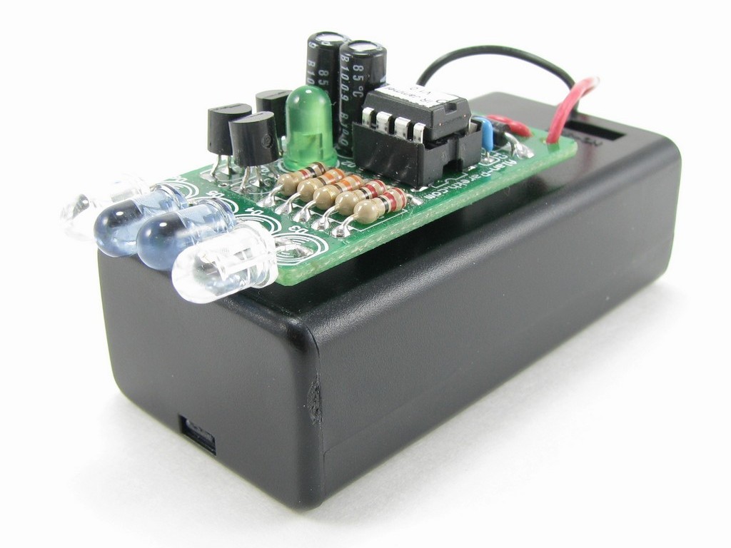
The IR Jammer project is microcontroller-based; what this means is there is a small self-contained computer that controls the unit. The IR Jammer will cause most infrared remote controls to stop working. This means that you could prevent someone from changing the TV channel or adjusting the volume on the stereo, etc. It does this by pulsing 4 high-power IR LEDs at specific frequencies that are used by most IR remote control systems. The frequencies configured are the 6 popular ones, 30kHz, 33kHz, 36kHz, 38kHz, 40kHz and 56kHz. Of course, this is harmless fun and when you turn the device off or point it away from the jammed device everything will be back to normal.
The operation is very simple: Just press the single button on the IR Jammer and it will blast IR frequencies for 30 seconds. Pressing the button again will add 30-second increments to the internal timer. So if you need to secretly prevent someone from changing the channel during the commercial you could hit the button 4 times to give you 2 full minutes of jamming.
Device Features
- Small and compact; the physical size is the same as a 9-volt battery. This makes it easy to conceal.
- Universal coverage since it covers the 6 main IR remote frequencies. Most existing IR jamming projects only target one frequency.
- Easy to aim since there are 2 wide-beam IR LED and has good distance because of the 2 narrow-beam IR LEDs.
- Provides lots of non-destructive fun because when the jammer is turned off there is no damage to any of the systems that were jammed.
- Great project to learn soldering since all components are through-hole devices.