lamp2 - 3
The lamp in its resting pose

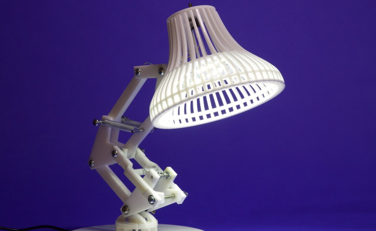
If you’ve ever seen a Pixar movie, then you’re probably familiar with the bouncing little lamp that squashes the ball during the title sequence. This lamp, called “Luxo Jr.”, was the main character of one of Pixar’s first short films, and has since become an iconic symbol of Pixar movies. There’s even a 15-foot-tall version of Luxo Jr. outside Pixar’s main atrium.

The 15-foot Luxo Jr. outside Pixar's main building (source: Michigan Daily)
The 15-foot Luxo Jr. outside Pixar’s main building (source: Michigan Daily)

In this project, you’ll build your very own Luxo Jr. lamp. This lamp has two white LED strips as its light source, and is a perfect size for your desk or study area. A small toggle switch on the top turns the light on (I used a toggle switch because I never really liked the twisty ones on most lamps). The body of the lamp is made from laser cut acrylic pieces, so you’ll need access to a laser cutter for this project.

lamp2 - 5
A toggle switch illuminates LED lights in the head of the lamp.

To make the lamp, first I designed everything in SolidWorks to get a sense of how the mechanism would work. I took care to only design parts that could be cut with a laser cutter (i.e.: making every part out of a flat sheet, and only using standard thicknesses for parts, in this case ¼” and “). I also accounted for the kerf of the laser in these files.

Then I exported .dxf versions of each part and brought those into Illustrator where I copied them accordingly and nested them efficiently. I’ve included the Illustrator files that can be sent directly to the laser cutter, and I’m also providing the SolidWorks model and .dxf files in case anyone wants to tweak or customize the design.

lamp2 - 4with ball
This design allows for surprisingly expressive poses.

As always, if you make this project please let us know how it went in the comments section below!

DOWNLOAD LINK: Luxo_Lamp_Files

Project Steps

Download the files

Download the zip file linked above. Included are the Illustrator files, DXFs, and the original SolidWorks model.

Gather supplies

Get all your materials and tools together (they are listed in the sidebar above).

Cut the parts

Cut the parts on a laser cutter. The thickness of the acrylic is specified in the file names.

Make the swivel joint

Construct the swivel joint using the photos as a guide. This mechanism has one disk attached to the base, and one disk attached to the armature of the lamp. Connecting them is a small component made from three pieces, which looks like a bobbin. This component keeps the disks together but allows them to rotate, and also has a hole through the center to allow the wires to route through it.

There isn’t really a best way to make this assembly, just sort of dry-fit everything together (put it together without glue) at first and see in what order things need to be glued together.

It’s also not the end of the world if the lamp doesn’t swivel (you can simply rotate the whole base instead).

The completed swivel joint assembly is shown in the third photo.

Build the base

Stack the two large ¼” disks on top of each other and glue them.

Glue the swivel joint assembly to the base by inserting the tabs into their matching slots.

Assemble the lower spring bar

Stack a short-hole-plate and a long-hole-plate together and glue them as shown in the first photo. Repeat so you have four of them.

Stack and glue the bent bar pieces as shown in the second photo.

Glue a hole-plate to each end of the bent bar as shown in the second photo.

Add a short section of threaded rod and springs as shown in the third photo.

Assemble the struts

The two rear struts are made from three stacked pieces of ⅛” acrylic. These struts have a channel that runs through them to rout the wires.

Construct the linkage

To make the linkage, I used 10-24 screws with washers in between the joints, and locknuts to secure everything. On the base joint and the head joint I used wing-nuts instead of locknuts for easy adjustment, and also added rubber washers to make the joints pivot smoothly and also lock securely into place when tightened.

Not that the third strut is simply a piece of ¼”, thus washers will need to be added to make up the difference in thickness. This strut has a hole for a short piece of rod which you need to cut and insert. You may need to drill out the hole so that it fits snugly. This rod is for mounting the upper two springs.

Speaking of springs, now is a good time to add them. Finding the right springs may be difficult, I’d suggest getting an assortment and trying different combinations until you get one that works.

Make the lamp shade

To make the lamp shade, start by gluing the shorter ribs to the LED mounting disk (the one with the three holes in it) and the secondary lamp ring (the large ring with notches, not holes).

The long ribs and short ribs alternate, so make sure to leave one notch between each short rib.

At this point, add the primary lamp ring (the large ring with the holes) to the bottom.

Next, add the long ribs, one of which has a loop in it to mount to the armature. There are two structural pieces which can be glued on either side of this piece to strengthen the joint.

Add the LEDs

Cut two short lengths of the LED strip and use thin-gage wire to link them together.

Solder a long section of wire to the end of the first strip, leaving a break in one wire to add the switch.

Stick the LEDs to the LED mounting plate and run the wires through the holes.

Mount the switch

Solder in the switch, and secure it to the switch mounting plate.

Run the wires out the side of the lamp right next to the rib with the hole, and put the switch mounting plate on the back of the lamp shade.

Attach the lamp shade

Attach the lamp shade to the rest of the armature.

Rout the wires

Run the wires from the lamp shade down the armature by sliding the wires through the channels in the struts.

Feed the wire down through the hole in the swivel joint and through to the bottom of the base.

Connect the power supply

Solder the power cable to the ends of the wires. Make sure to put heat shrink tubing on the wires before you solder them together!

Glue the power cable into the slot underneath the lamp with super glue.

Add a strip of tape over the slot to cover it up.

Test it out!

You’re done! Plug in your lamp and test it out!