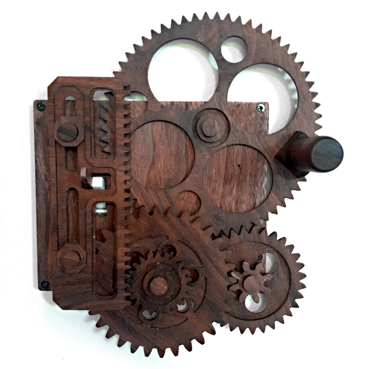
I was initially inspired to make a gear-driven light switch when I saw one that a friend of mine bought online, which I later learned was inspired by a “light switch complicator” that Ernie Fosselius showed at Maker Faire. You turn the crank, and a series of gears translates a linear slider that flips the switch.

I found this to be a relatively easy project to design. It looks complicated, but with the help of gear creator sites like geargenerator.com, the hardest part was creating a layout to keep everything compact. You can cut the files on a CNC or a laser cutter in hardwood or whatever materials you think look nice. Here’s my version in solid walnut. It’s a fun project that can be done in an afternoon.

Project Steps

1. Cut the pieces

Download the plans and cut all pieces out with either a CNC or laser cutter for precision. All screw holes should be countersunk, and functional pockets should be about half the depth of the material they are in.

Gears, spacers, and the switch flipper all need to be the same thickness. The faceplate, wall plate, end caps, switch extender, and track alignment spacers can all be a different thickness if needed. A thickness of ¼” for gears and ⅛” for plates and extender is a good place to start.

2. Make the shafts

Start by gluing the end caps onto five ¼” dowels, as square as possible. Leave these long: 2″ or longer. You’ll cut them to the correct length later.

Glue two of the octagon-shaped spacers to the end caps. These two will ride in the flipper tracks to keep it aligned.

3. Glue spacers

Glue the gear backs to the back of the faceplate. These should be the same thickness or thinner than the wall plate; they’re to give the faceplate holes more depth to glue the shafts in later. You can use the wall plate as a guide for placement when gluing.

Glue together and set aside the two sets of spacers that will be used under the flipper track. The two solid spacers go together as a pair. The spacer with the pocket and the one with the matching cutoff go together as shown.

4. Glue the gears

Glue gears 2 and 3 together. The tooth alignment does not matter at this point.

Glue together gears 4, 5, and the large round spacer. Use a shaft to align all the center holes to guarantee smooth rotations, but be careful not to glue the gears to the shaft. They will need to spin freely on it later.

5. Mount the gears

Add the 3 shafts that only have end caps to each of the gear sets. Sand the shafts if needed to make the gears spin easily without friction.

Slide the gears into position on the faceplate. At this point, turning any of the gears should rotate the whole assemble easily. Out-of-square gear shafts will cause binding.

6. Mount the switch flipper

Glue the two sets of octagon spacers from earlier to the faceplate. These are offsets for the flipper track to sit on. Align the lower set so the cutout allows clearance for gear 4 to spin.

Inset the two shafts with the octagon track spacers into the flipper track. Then insert the flipper track into the stacked spacers.

Check alignment. Rotating gear 1 should easily move the track up and down. If there’s friction, try sanding the sides of the spacers that ride in the track to create clearance.

7. Glue the shafts

Align the gear positions so the smallest (¼”) hole on gear 1 is in the upper right corner position when the center hole on the flipper track is centered over the switch hole on the wall plate.

Once everything is aligned, mark the depths on each shaft, remove, add wood glue, and reinsert. Double-check alignment before the glue dries.

8. Add a handle

Drill a ¼” hole and insert a dowel in a piece of rounded stock to use as a handle. For mine I used a ½”×½” scrap, rounded on a belt sander.

Insert and glue the handle into the ¼” hole in gear 1.

9. Prepare the light switch

Remove the wall plate from a single standard light switch.

Using the screws for the original wall plate, attach the new wall plate. Make sure the screws are flush or below the surface. If not, countersink the screw holes. The faceplate must sit flat on the wall plate.

Using super glue, attach the switch extender. Make sure the switch can still move freely to change positions. Leave it long and cut it to size after attaching the faceplate with gears attached.

10. Mount it on the wall

Attach the faceplate to the wall plate with small wood screws in each of the four corners. The lower right screw hole should be accessible through the holes in gear 2 based on the rotation.

Depending on thickness of your wall plate and faceplate, you may need to grind your screws short. Again, make sure they’re flush or below the faceplate surface, or the gears will not turn smoothly.

You’re done. Now turn the handle to unnecessarily complicate your switch flipping!

Going Further

You can use the free calculator at Gear Generator (geargenerator.com) to design your own gearing, or to create an all-new light switch complicator.

I’ve made this twice now, once with my CNC and once with the laser, and both ways worked without any special modification. I thought for sure I’d have to change something for it to work with a laser but I was able to engrave the pockets just fine.

I guess you could 3D-print the pieces as well, but 3D-print stuff looks like junk and why would you want junk on your wall?