M25 Secret Knock Gumball Machine opener

YouTube player

One of the best things about exhibiting at Maker Faire is giving attendees a challenge. For the 2010 Maker Faire Bay Area, I decided to combine a past project of mine, a door lock that opens only when you give a secret knock, with a standard crowd pleaser: candy.

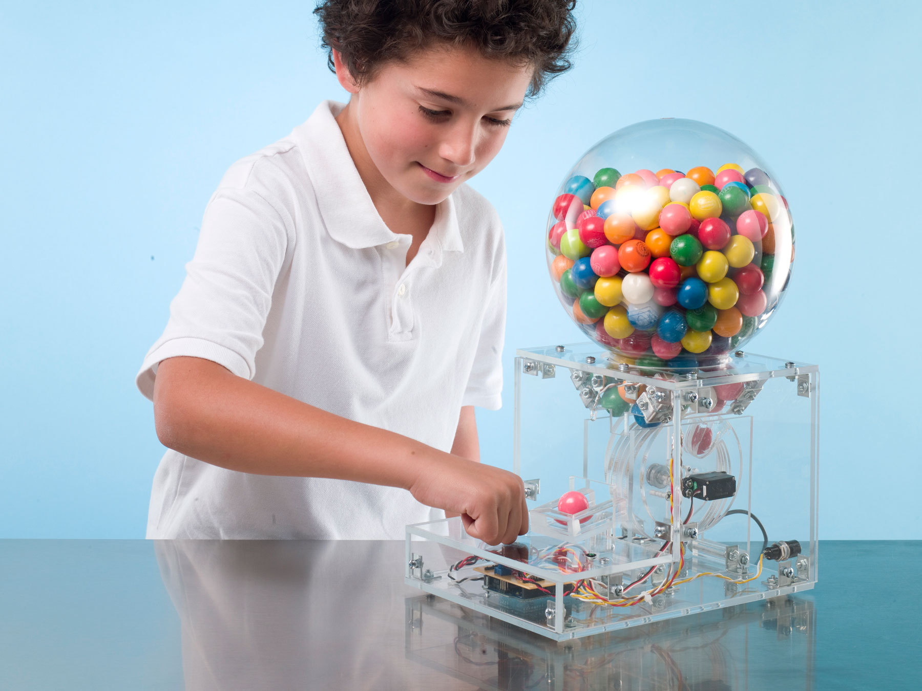
The result was this Secret-Knock Gumball Machine, which tempted and tested the crowds at Maker Faire to guess the right rhythm and receive a treat. Since the knock was not terribly secret (I happily handed out hints), it distributed hundreds of gumballs over the event’s two days.

The “secret” knock defaults to the famous “Shave and a Haircut” rhythm, but you can program custom knocks by simply pressing a button and knocking a new pattern. The machine only listens for the rhythm, not the tempo, so the correct knock will dispense a treat whether you perform it fast or slow.

Inside the machine, a piezo sensor picks up sounds from the front knock panel, while an Arduino microcontroller recognizes the target pattern and controls a servo-driven gumball-dispensing wheel. You can build the Secret-Knock Gumball Machine with its inner workings visible or hidden, depending on whether you want to show off the mechanism or keep it a mystery.

Downloadable files

MAKE: Amends

In MAKE Volume 25, page 95 the part number listed for the clear plastic globe from 1000bulbs.com was incorrect and should have read #3202-08020.

Project Steps

Build the case.

Download the templates and print them at full size. Transfer to plywood or acrylic, and cut all pieces to size. Mark all screw and rail locations for later drilling and placement. To avoid confusing or flipping parts, temporarily mark the outside of each part with masking tape. Sand all edges smooth.

Use a 4″ hole saw to cut the hole in the top plate as well as the 7 dispensing wheel disks (2 stir plates and 5 center disks). You can use the remnant of the top plate hole as one of the dispensing wheel disks. Drill the 1/4″ axle holes (which are off-center on the stir plates) as shown on the template.

TIP: To minimize chipping when working with acrylic, support the work well, tape both sides of all cuts, and use fine-bladed saws at low speed — or have your local plastics retailer cut the pieces.

Attach 3 rails to each side panel where indicated on the template. The front and back rails are 3/16″ from the edge. The 2 side pieces should mirror each other, with rails on the inside of the case.

NOTE: Unless otherwise specified, all attachments in this project are made with #8 3/4″ wood screws, and holes should be pilot-drilled to prevent splitting.

Attach the bottom panel and front panel to the side panels.

Drill holes for the power plug and programming switch in the back panel, then attach it to the side panels.

Test the knock plate, top panel, and access panel for fit, and pre-drill the holes, but don’t attach them yet.

Build the gumball funnel.

Attach the top and bottom rails to each funnel end piece.

Attach the funnel side pieces to the funnel ends. Be sure to put the rails on the outside of the funnel.

Attach the completed funnel to the bottom of the top plate with 4 screws.

Build the dispensing wheel.

Make a sandwich of round plates: the 5 dispensing wheel plates stacked in the middle and one stir plate on each end, with the stir plates rotated 30° from each other. Push the brass tube through the axle holes and use an L-square to check for true.

Clamp, pre-drill, and secure the whole stack with a #12 1-1/4″ wood screw on each side.

Clamp the dispensing wheel (in a drill press if available) and drill a 1″ deep hole using a 1″ Forstner bit. The hole should point directly down toward the axle, centered between the stir plates and equidistant between their peaks. To help gauge the right hole depth, place a masking tape flag 1″ from the bottom of the drill bit.

Toss a 1″ gumball in the hole to check for fit. It should fall in and out easily, and the top of the gumball should sit flush with the wheel.

Attach the servo horn (the X-shaped plastic piece that connects to the servo shaft) to the center of the wheel using four ½” #2 screws. Space the screws so that they don’t intrude into the 1″ hole drilled in the previous step. To center the horn, sight its drive-shaft mounting hole through the axle hole of the dispensing wheel.

Mount the dispensing wheel.

Before attaching the servo, we need to zero its rotational position using the Arduino. Download and install the latest version of the Arduino application from arduino.cc/en/Main/Software, and attach the Arduino to your computer with the USB cable. Use 3 solid-core wire leads to temporarily connect the servo’s red wire to Arduino +5V, the servo’s black (or brown) wire to Arduino ground (GND), and the servo’s white (or orange) wire to Arduino Digital Out 7.

Download servo_reset.pde, open it in the Arduino application, and upload it to the microcontroller. The servo should rotate fully one way, then the other, then stop.

Remove the wires connecting the servo to the Arduino. Use the servo’s supplied mounting screws to attach it to the dispensing wheel right side plate, with the servo shaft centered to line up with the 7/32″ center hole in the left side plate. Before screwing, fit the included rubber bushings and metal grommets into the servo mounting holes to provide strain relief, with the curved edges of the grommets facing the wood. It’s OK if the screw points run out the other side of the plate.

Orient the dispensing wheel next to the right side plate so that the gumball hole tilts back 45° toward what will be the back of the machine. Slide the servo horn over the servo shaft and secure it with the included servo horn screw that runs through the center of the horn.

Use a hacksaw or pipe cutter to cut a 1-7/16″ length of brass tube for the axle. Insert the tube into the dispensing wheel axle hole. It should be flush with the stir plates.

Hammer the T-nut firmly into the hole on the dispensing wheel left side plate, on the outside (not the wheel side).

Place a washer on the 3/16″×1-1/4″ bolt, thread it entirely through the T-nut, and tighten the bolt firmly. Place three 3/16″×3/4″ washers on the inside of the bolt.

Insert the end of the bolt into the dispensing wheel axle. Attach the left and right side plates to each other with the 2″ dispensing wheel rails. If there’s a lot of play between the T-nut and the dispensing wheel, add an additional washer before screwing the plates together.

Assemble and test the electronics.

For all connections, refer to the schematic layout (SNGM_schematic.pdf) and circuit board layout (SNGM_layout.pdf) at left.

Cut and strip leads for all off-board components. You’ll need four 5″ leads for the indicator LEDs and four 14″ leads for the power connector and programming button. If you’re making a transparent case, you’ll also need two 12″ leads and two 16″ leads for the white LEDs.

Cut the breakaway header pins into rows of 8, 6, 6, and 3. On all but the 3-pin header, use needlenose pliers to push the pins flush with the plastic spacer.

Solder the headers in place on the perf board, following the layout diagram SNGM_layout.pdf. The 3-pin header’s long pins should point up, for connecting the servo, while the other header pins should run down through the bottom of the board for plugging into the Arduino.

Solder the rest of the components to the perf board following the layout or schematic diagram SNGM_schematic.pdf. Pay special attention to the polarity of the LEDs (longer leg is positive) and power connector (center pin is positive). Omit the 2 white LEDs and 100Ω resistors if you’re not making a transparent case.

Plug the completed shield into the top of the Arduino, aligning the 8-pin header with digital pins 0–7. Plug the servo into the 3-pin header on the shield, taking care to observe the polarity (because plugging the servo in backward can damage it).

Connect the Arduino to your computer with a USB cable. Download the code file secret_knock_ gumball_machine.pde and upload it to the Arduino.

After you upload the sketch (or apply power for the first time) all the LEDs should light, and the servo should rotate the dispensing wheel to its start location. When the lights go out, it’s ready to listen for a knock.

Turn the sensitivity potentiometer down until the green LED stops blinking. If the light stays on no matter how far you turn it, check the piezo sensor wiring for shorts or bad connections.

For testing, adjust the pot so that the green light stops blinking without any input, but gently tapping the knock sensor makes it blink.

Tap the “Shave and a Haircut” rhythm. The green LED should blink and the servo should rotate. If you included the white LEDs, #1 should blink and #2 should stay lit for a few seconds. If an incorrect rhythm is entered, the red LED should blink.

Press the programming button, and both red and green LEDs should light. Tap a new rhythm, release the button, and wait a second. The red and green lights should echo the rhythm visually, and tapping this new rhythm should rotate the servo. Resetting or unplugging the Arduino will revert it to the default “Shave and a Haircut.”

Wire and complete the case.

Secure the top panel to the rest of the case with 4 screws. Align the panel so the offset 4″ hole is toward the back of the device.

Secure the dispensing wheel assembly to the bottom panel with 2 screws. Rotate the dispensing wheel to check for clearance against the back panel and the funnel, and remove material wherever it hits the wheel.

Attach the gumball tray support directly in front of the dispensing wheel, with the support’s angled end on top, and inclining down toward the front of the case.

Unplug the shield from the Arduino. Attach 4 rubber feet to its underside and use two 4-40 bolts and nuts to attach it to the bottom panel. Insert the screws up from the bottom through the pre-drilled holes, and thread the nuts on top. Do not overtighten the nuts.

Attach the knock sensor to the center back of the knock plate using two ½” #2 screws. The side of the piezo buzzer with the center hole in it should fully contact the back of the knock plate, and the screws shouldn’t penetrate through to the other side of the wood. I attached the sensor “upside down” with its mounting tabs away from the wood to keep the screws from running through, but the sensor will function facing either way.

Insert the LED holders into the front of the knock plate and slide the red and green LEDs into the holders from the back.

Attach the power plug and programming button to the back of the case with their mounting hardware.

If you’re making a transparent case, attach the white LEDs to illuminate the action. Tighten a small cable tie around the base of each white LED and secure it in place with a thumbtack. Place LED #1 behind the right side pillar pointing inward, and LED #2 on the bottom front of the dispensing funnel, pointing to the gumball tray. Use the remaining cable ties to secure and manage the cables inside the case.

Screw the knock panel into place.

Screw the gumball tray sides to the gumball tray, and screw the tray down onto the tray support post. Before attaching it permanently, check for gumball clearance against the dispensing wheel and the access panel.

Stick a rubber foot on each bottom corner to prevent the machine from sliding around as people knock. Finally, attach the access panel. You’re done!

Set up your machine.

Plug the power adapter into a handy outlet and plug the other end into the back of the machine.

Fill the plastic globe with your favorite 1″ gumballs (or other candy balls) and put it on top. To prevent spilling the balls all over the floor, put a piece of thick cardstock or cardboard over the hole in the globe, invert it in place, then slide the card out.

Program your new secret knock or leave it with the standard “Shave and a Haircut” knock.

Knock and enjoy!

TIP: To make the machine more responsive, loosen the screws that hold down the knock plate and gumball tray, so that they move and clatter when you knock. Or add some flare to your machine with these stencils.

Conclusion

Treat Selection

The 1" ball is a vending industry standard for not only gum, but also jawbreakers and other candies, bouncy balls, toy capsules, and empty capsules that you can fill with your own small objects.

An 8" globe holds about 200 gumballs, which are usually sold in quantities of 850 — but you can also buy 1" gumballs by the pound at bulk candy stores, and there are sellers on eBay that offer them in smaller quantities. I also found a box of 500 gumballs at Smart & Final.

This project first appeared in MAKE Volume 25, page 92.