M35_Proj_MyKeepon_Opener_03

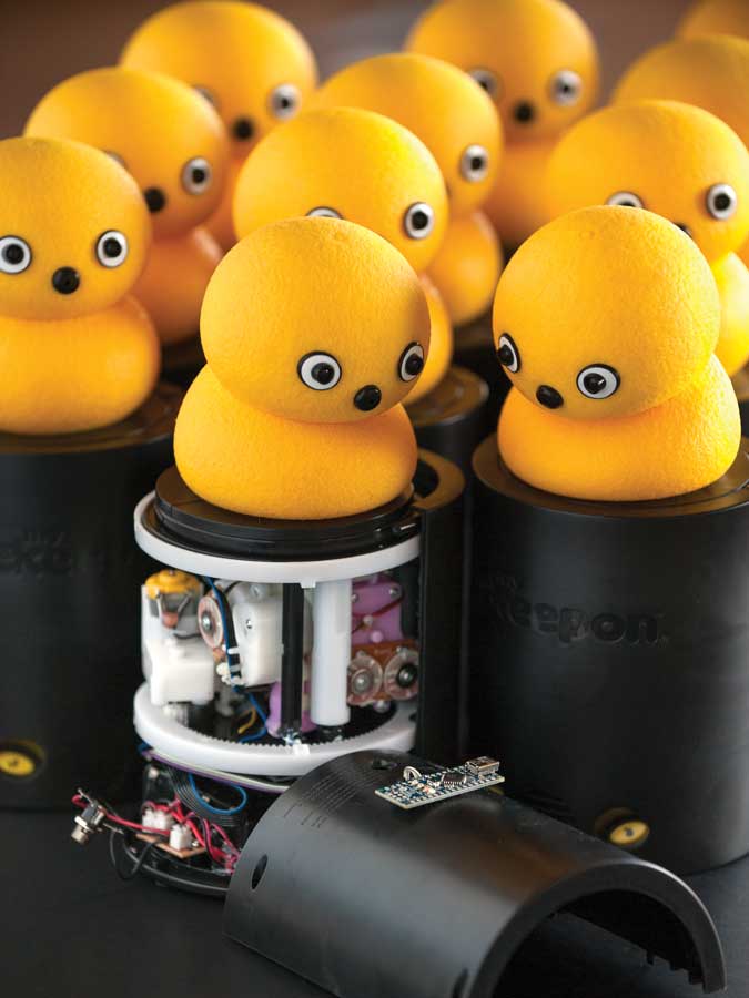
Designed by scientists studying social development, Keepon Pro is a small, “friendly” robot that interacts with children. My Keepon is a low-cost version released by BeatBots and UK-based toy company Wow! Stuff. Unlike the original Keepon, My Keepon lacked the ability to be teleoperated — until now.

These instructions show you how to connect an Arduino to My Keepon’s electronics, so you can control it using just about any sensors, devices, and interfaces you can imagine!

The basic principle of this hack is to send commands to the microcontrollers inside My Keepon over the I2C bus. I2C is a two-wire serial interface commonly used for communication between embedded systems and peripherals (wikipedia.org/wiki/I2C). We’ve provided access to all commands for setting motor speeds and positions, playing sounds, and retrieving information about audio perception, motor EMF, and encoder positions.

YouTube player

Be warned: performing this surgery will void your warranty, so please don’t try to take it back to a retailer after doing this. But it’s a straightforward procedure, and you’ll easily be able to impress other Keepon fans with your new dance choreographies, Kinect mash-ups, and Wiimote-control demos.

In these instructions, we show you how to do this modification in the simplest way, with only a single additional hole drilled into the cylindrical base. You can go further by installing the Arduino Nano board inside the battery compartment, running the USB cable directly into the base, and powering My Keepon with an adapter. But if you want to continue powering the My Keepon with batteries, or if you plan to use Arduino Uno/Mega shields (for wireless communication, additional sensors or actuators, etc.), you’ll probably want to “backpack” the components on the base as shown here.

What will the next generation of Make: look like? We’re inviting you to shape the future by investing in Make:. By becoming an investor, you help decide what’s next. The future of Make: is in your hands. Learn More.

Project Steps

Open the skull and expose the brain.

Remove the 4 screws securing the back half of the My Keepon cylindrical base. Gently remove the back half of the base, leaving the guts and bottom plate in the front half.

Unplug the ribbon cable running into the control board.

Gently lift the bottom plate (with battery compartment, encoder, and cables) out of the front half. Since there are encoder pins on the control board in contact with the encoder, you may need to lift the robot’s mechanical guts a few millimeters up out of the front half; keep the white plastic rings aligned when you do this. Put the bottom plate aside. Remove the clear plastic cover from the control board.

Attach the electrodes.

Cut 10″ or 25cm of 4-wire ribbon cable (or 4 separate 10″ lengths of thin/stranded/flexible jumper wire), and strip one end.

Identify the I2C bus pads on the top right corner of the control board, conveniently marked with a friendly silkscreened smiley face. Solder the ribbon cable to the 4 pads, keeping track of which wire you’ve connected to which pad: V (+ voltage), CL (clock), DA (data), G (ground). You may want to add some hot glue to keep the wire secure.

Close 'er up.

Widen the hole in the plastic cover to accommodate your new cable. Put the cover back on the control board, running your new ribbon cable through it. Reconnect the original white connector back to the control board.

Place the bottom plate back in the base, lifting the guts slightly if you need to, so that the encoder pins are centered on the encoder.

Close 'er up (cont'd).

Drill a hole in the back half of the cylinder, about 1cm above the power port, large enough to accommodate your ribbon cable. Thread about 1″ of your ribbon cable through the hole.

Place the back cover on the cylinder, carefully tucking away a fold of your ribbon cable so that it will have room to rotate with the mechanism. Replace the screws securing the back of the cylinder.

Attach the Arduino.

Strip 2mm–3mm of the ribbon cable

protruding from the robot and solder the 4 wires to the appropriate pins on the Arduino. My Keepon’s V pin connects to the Arduino’s A0 pin; CL connects to the A5, DA connects to A4, and G connects to GND.

Secure the Arduino to the back of the robot however you prefer (e.g. with double-sided foam tape or hot glue).

Pull the strings.

With My Keepon powered off, connect the Arduino to your computer with the USB cable. Flash the Arduino with the MyKeepon.ino source file at github.com/beatbots/mykeepon. Start the Arduino Serial Monitor (or another application written to talk to the robot) at 115,200 baud. When the Arduino’s code begins running, it waits to see voltage on the A0 pin (from My Keepon’s V pin).

Now power on My Keepon; the Arduino can now receive serial commands and translate them to the appropriate I2C messages for My Keepon’s controller. Happy hacking!

Going Further.

At our Github page you can find a Max/MSP control patch, a standalone application built from the patch, and an openFrameworks-based application for controlling multiple My Keepons. But you can send the command strings from any application or code of your own devising. Allowable command strings are here.

The Arduino also periodically sends back data strings from My Keepon’s I2C bus. You can change their frequency in the Arduino code here.