IRIS-3-half
Photo: Chris Schaie

This all started out as a quest for a better peephole for my shop door.

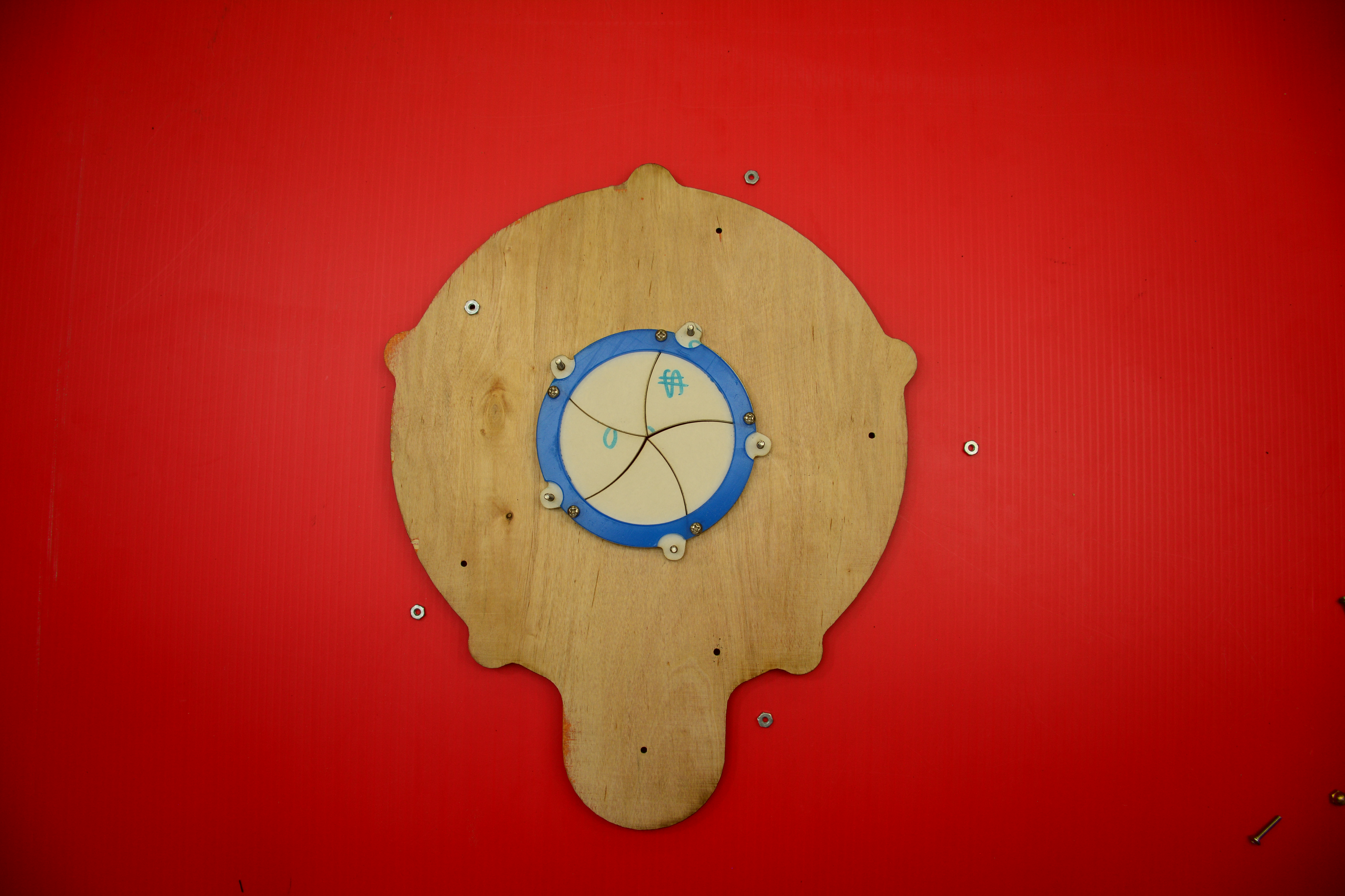
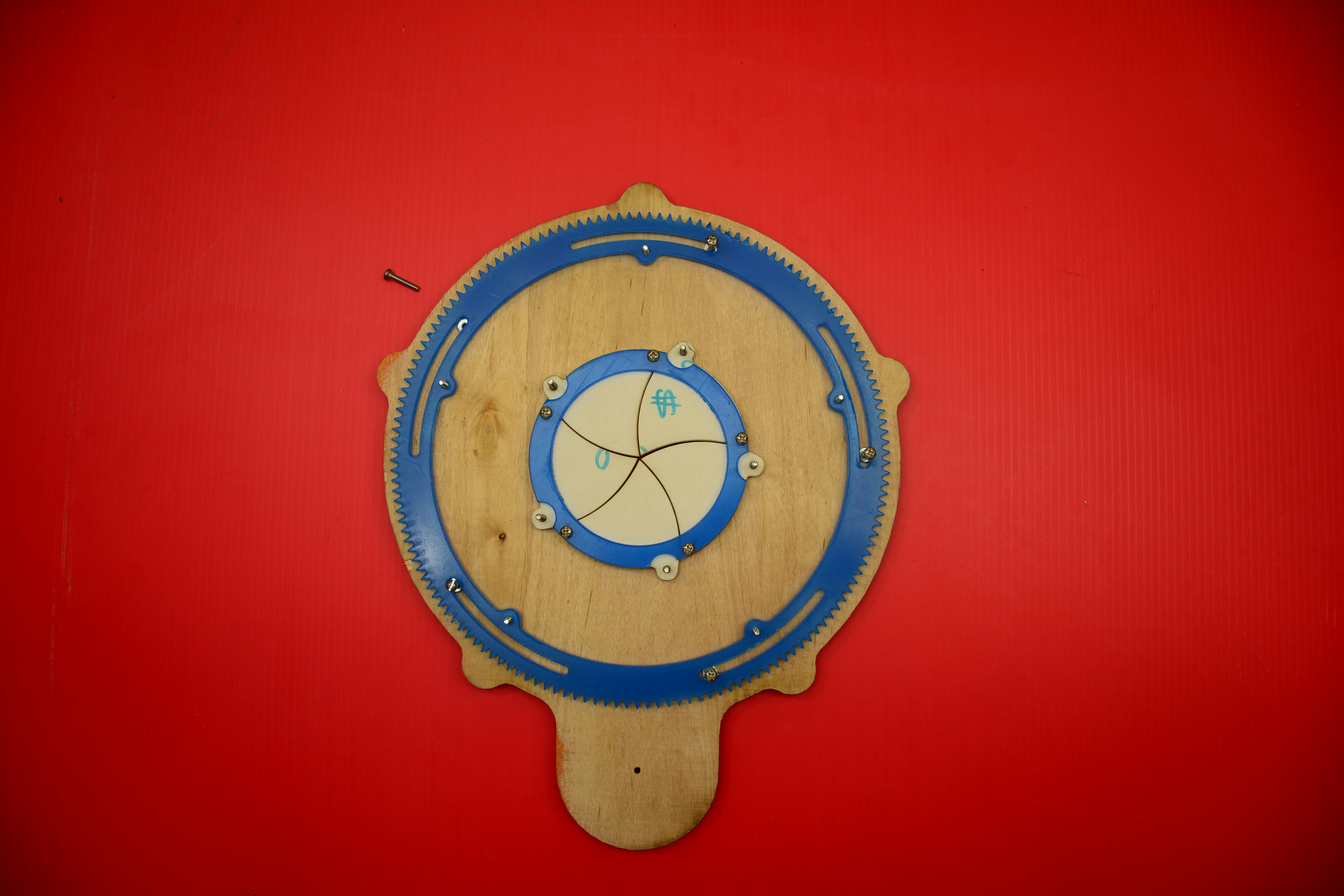
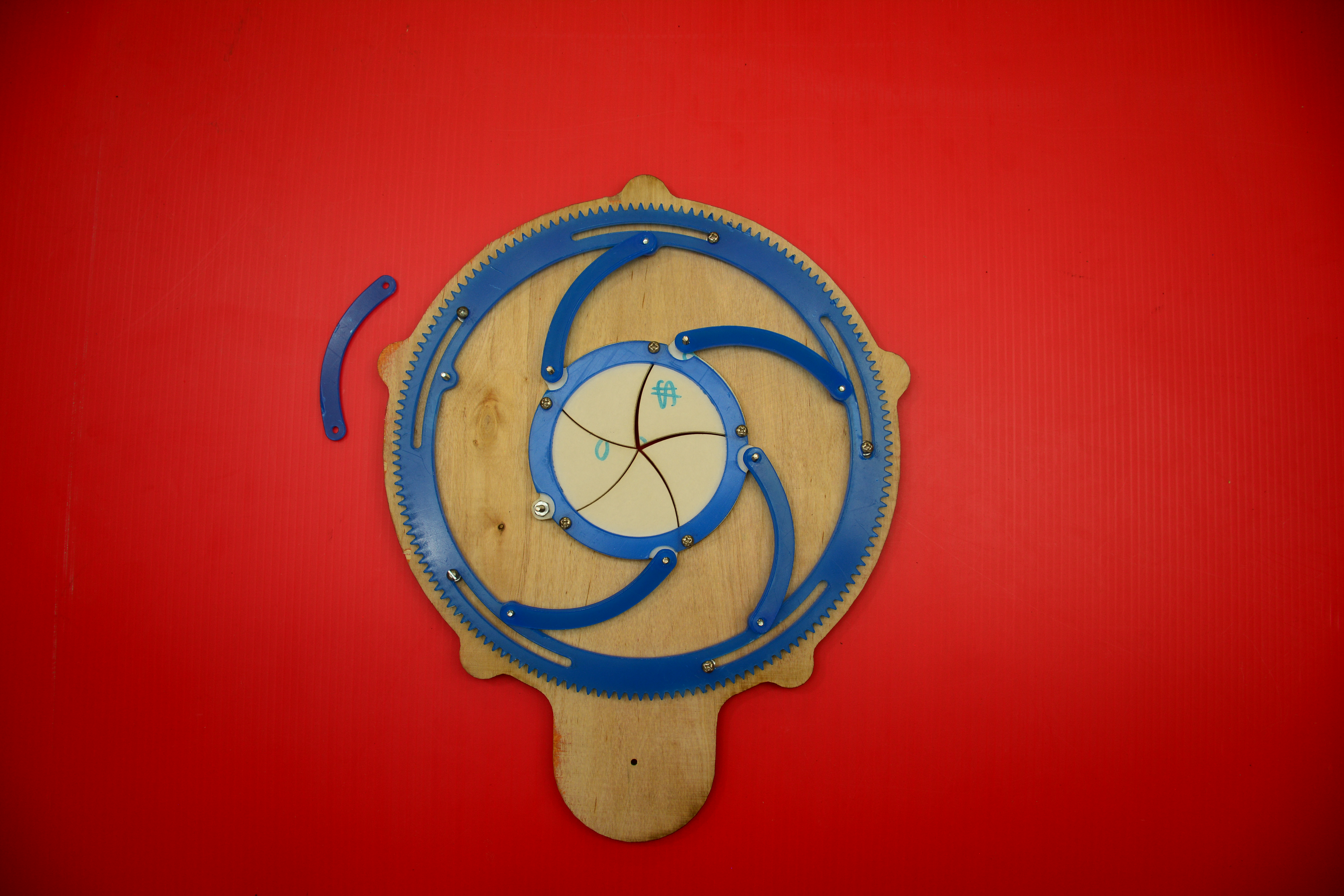
I was cruising the interwebs when I found a thread talking about irises. Most of the discussion was debating the pros and cons of a traditional interleaved camera iris in various projects. The biggest problem with that design is that it never entirely closes. Several of us started throwing out ideas for alternatives. Star Wars showed up a lot here (the sliding doors in the Death Star, the top hatch on the Millennium Falcon), and when I saw a drawing posted with curved panels that meet in the middle, this project was born.

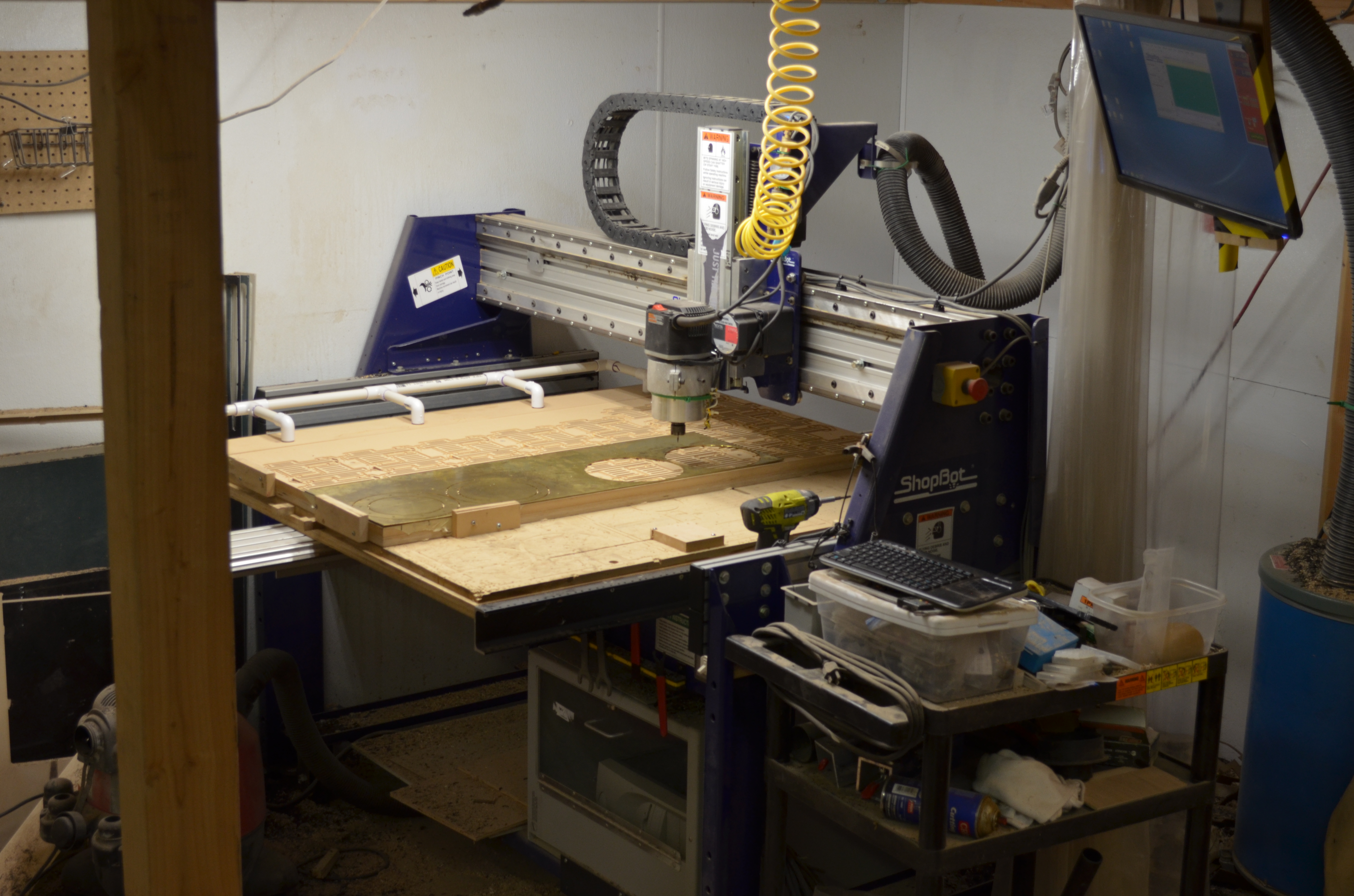
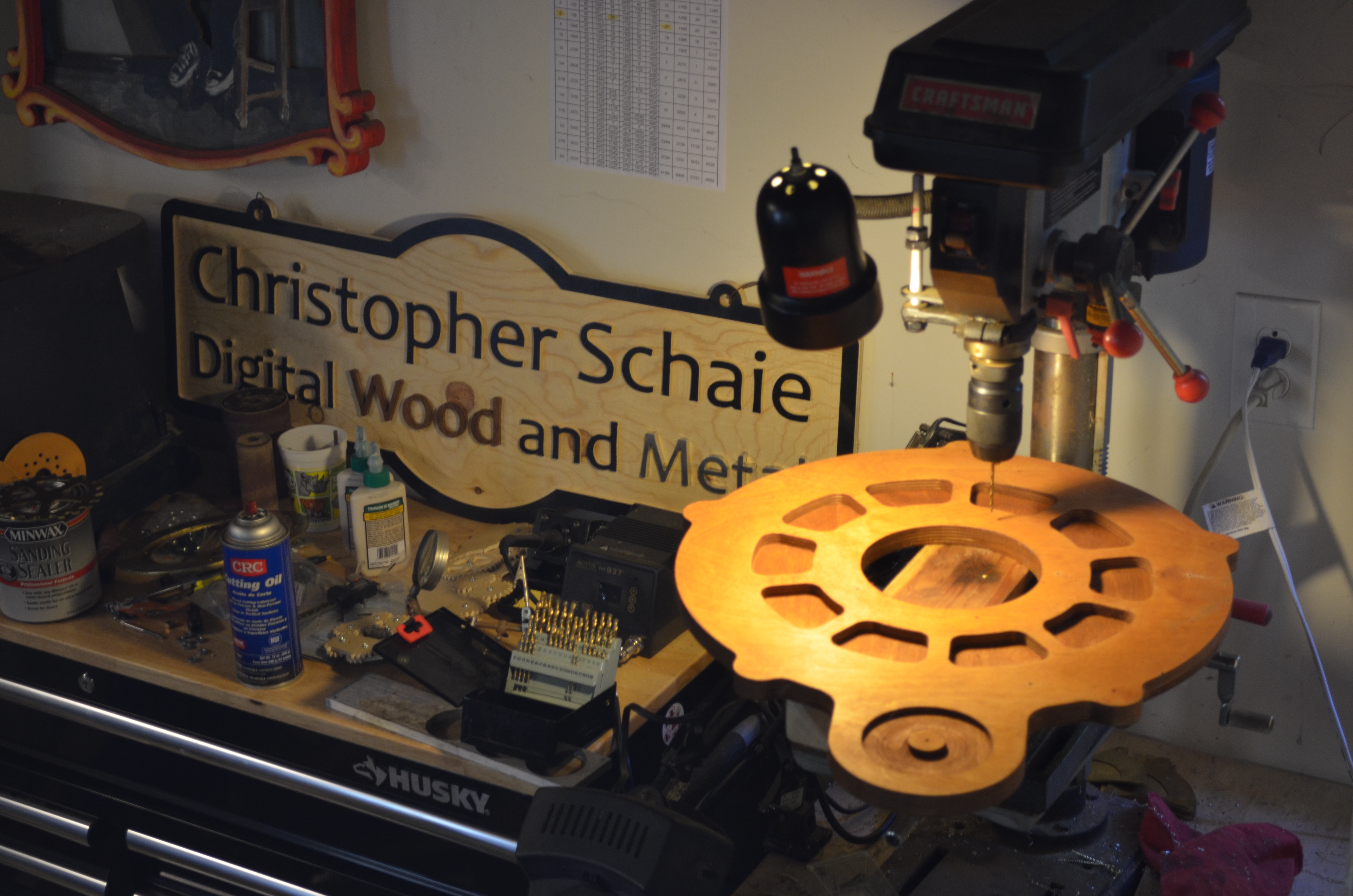
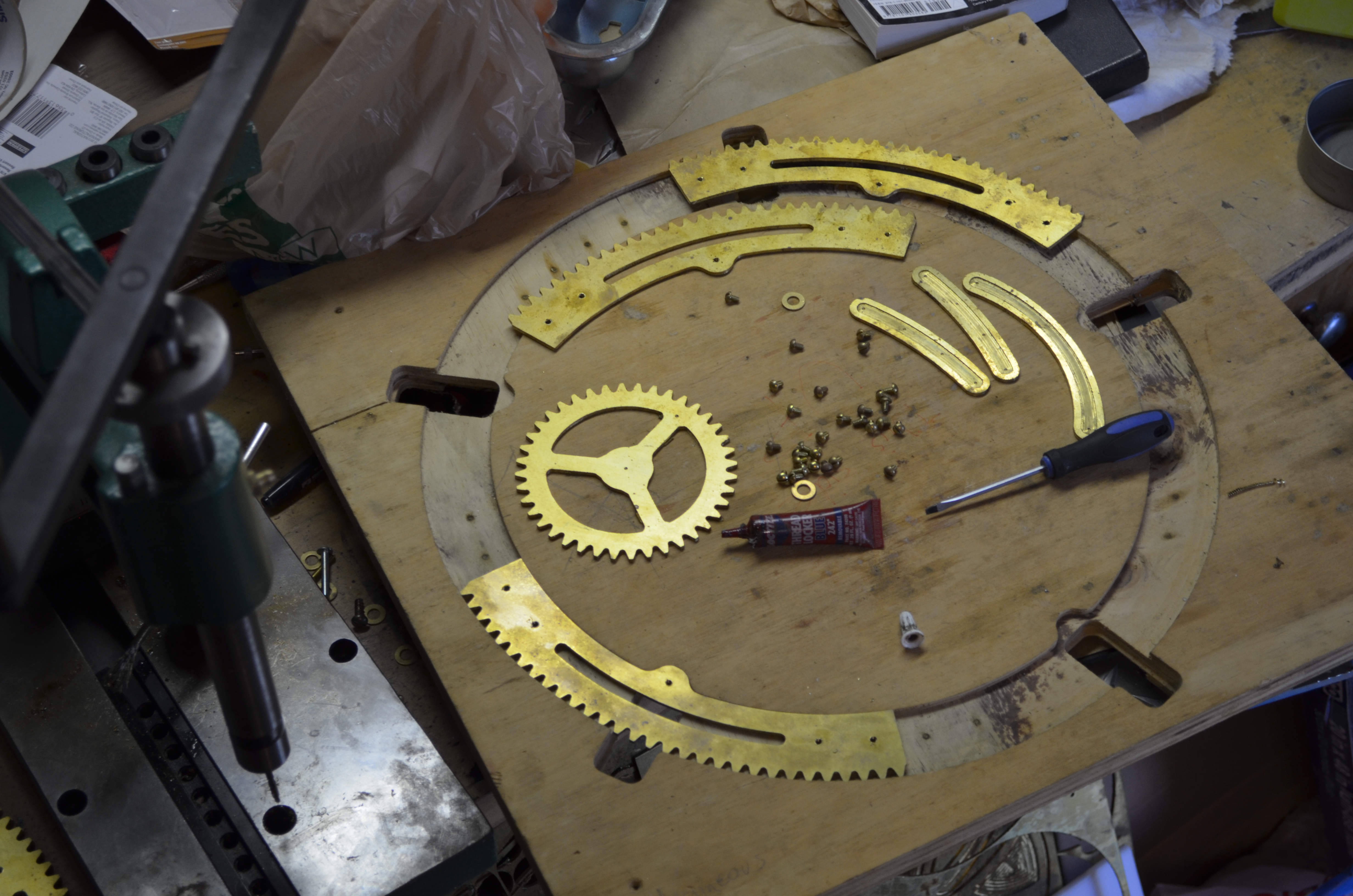
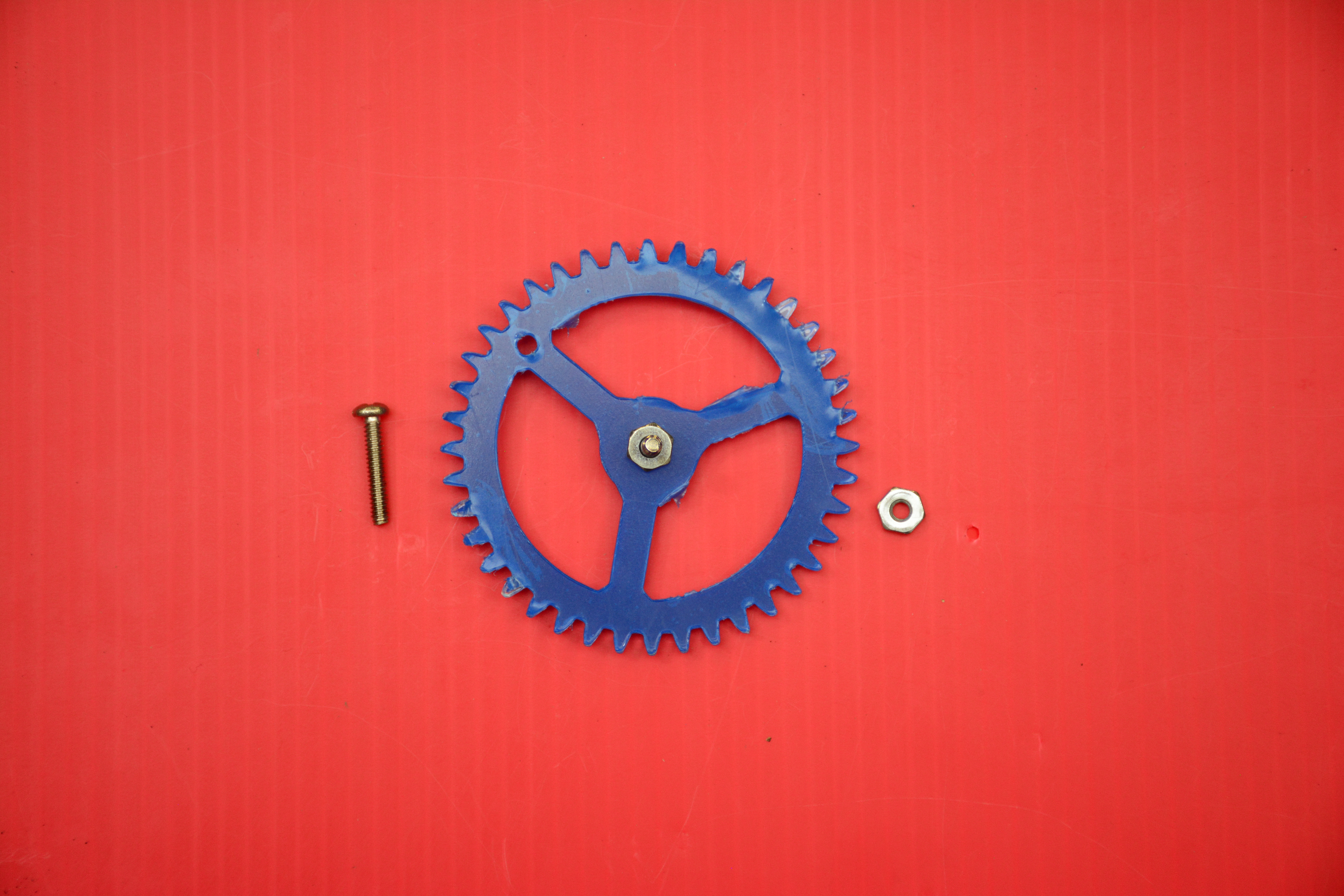
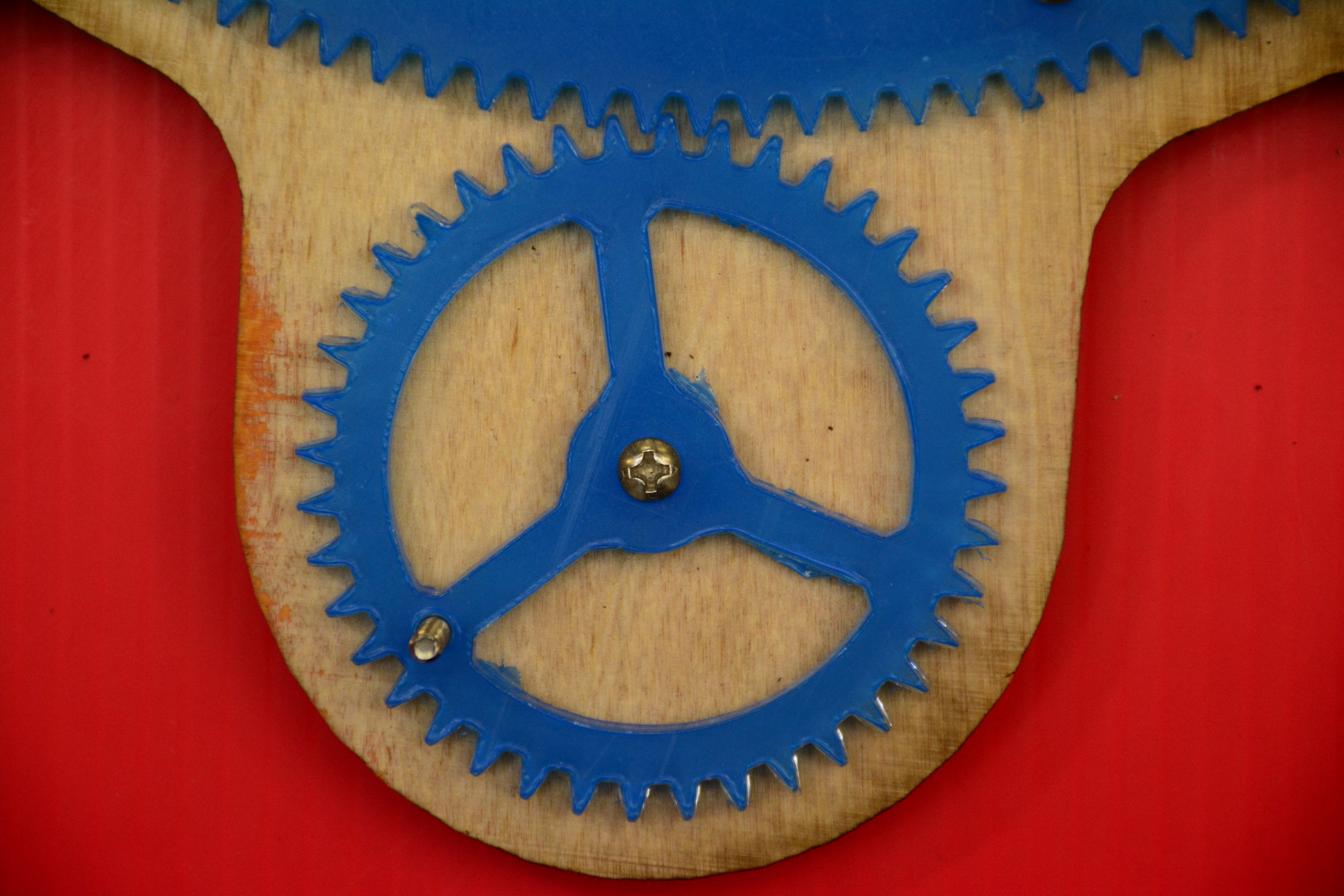
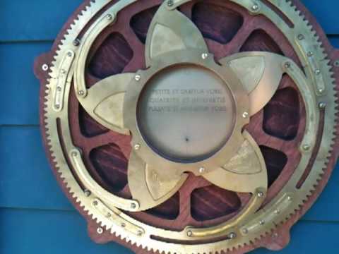
You can easily cut it on a laser cutter in acrylic, plywood, or hardboard. I cut mine from brass and ply on my ShopBot CNC router for about $70 in materials. In the Maker Media Lab, Matt Kelly and Anthony Lam made theirs from ¼” plywood and 1/8″ acrylic on an Epilog laser cutter.

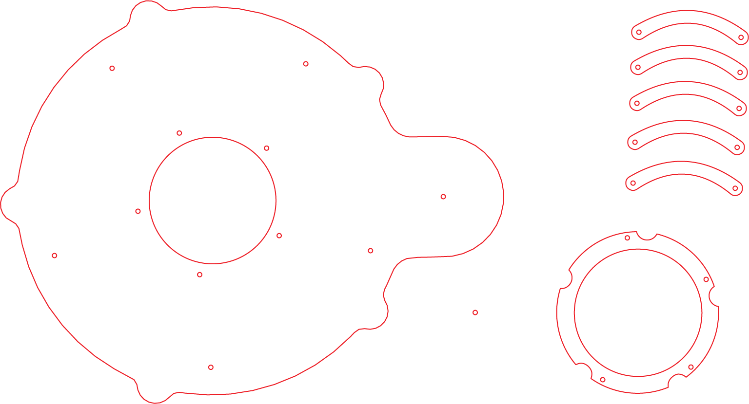
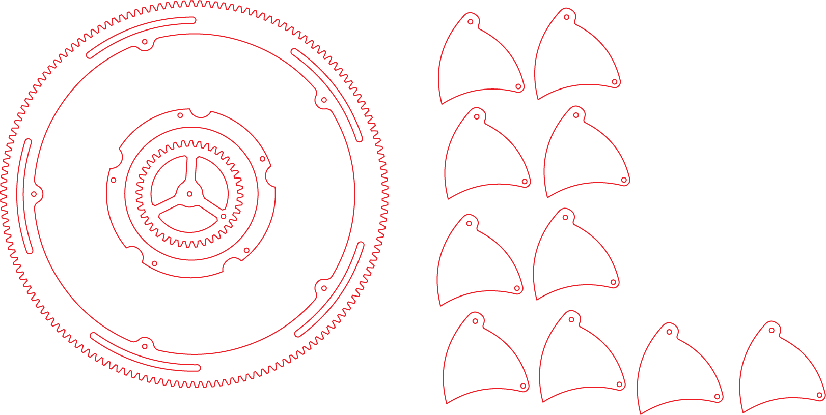
I’m sharing my design files so anyone can build it. Download the DXF drawings and CRV files here, and let’s get started.

YouTube player

Assembly3

Project Steps

Prepare files for cutting

Measure your materials’ thicknesses; then, in your CAM software, modify the files as needed to get good cut-throughs and still leave needed tabs.

For a laser cutter, change the decorative pocket cuts to an engrave pass, or eliminate them entirely.

Output the cutting files (G-code, or simple vector graphics for laser cutters) for your particular machine.

Cut the parts

I separated the cut files into groups that used the same bit: ⅛” for cutting out parts, ¼” for pockets, engraver for marking drill holes, and ½” for the plywood backer board.

You’ll need a way to hold the material to the bed of the router. If you stick the brass down with double-sided tape, you can use the router to mill holes for hold-down screws; this lets you place them where you won’t hit them while cutting.

Laser cutters may vary; we required multiple cuts on the same sheet.

TIP: To prevent scorch marks when laser-cutting wood, cover the cutting areas with blue painter’s tape.

Drill and tap holes

Drill holes as indicated on the assembly drawing.

Then tap threads in the #36 holes using the #6 tap (a bit of lubricant helps here).

Clean up the parts

Here’s where the spindle sander helps. Remove any leftover tab material, and use your files or deburring tool to clean up any rough edges.

For laser-cut wood, use 220 grit sandpaper to clean the charred edges, then 400 grit to smooth them. Higher grits (optional) will smooth them out even more.

Assemble the iris

Attach the inner ring, and one corner of each iris leaf, to the plywood with long #6 screws and a Delrin washer between each layer.

Assemble the actuating outer ring using short #6 screws, then mount it to the plywood by placing wood screws through the open grooves with brass washers behind.

Connect the 5 linkages using short #6 screws and washers.

Add the crank gear

For the handle knob, countersink the hole in the drive gear from the back, then use the flat-head screw to secure the drawer pull to the gear.

Finally, mount the drive gear with a wood screw and fender washer.

Mount it somewhere fun

To install the finished unit on a door or wall, I like to rough-cut the hole with a saber saw then use a flush trim bit (with bearing) to rout out the edges.

For exterior use, I made a brass porthole window the size of the aperture and glazed it to weatherproof it.