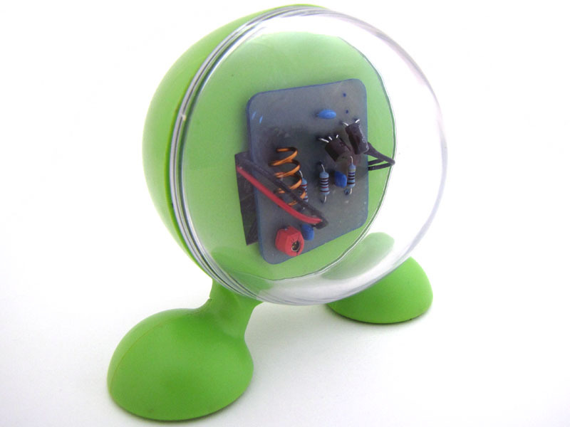
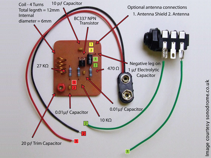
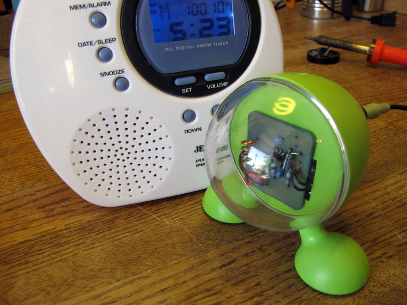
This circuit is commonly credited to Japanese multimedia artist Tetsuo Kogawa. It takes audio input through a 1/4″ phono jack and, constructed as shown, without the optional antenna connections, will broadcast an FM radio signal about 30 feet.

This is the standard model of Mr. Kogawa’s simplest FM transmitter, which is slightly more complex than his most basic design in that it includes a trim capacitor to adjust the transmitting frequency. It can be powered by a 9V battery and uses a hand-turned copper coil.

I’m using the PCB and parts from Sonodrome’s old kit, but the circuit is extraordinarily simple and could be built on perfboard or on a panel almost as easily. Sonodrome provides free PCB art if you want to etch your own board. Kogawa himself provides instructions for building the transmitter on an unetched copper-clad panel.

Project Steps

Prep case

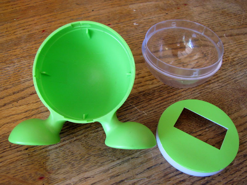
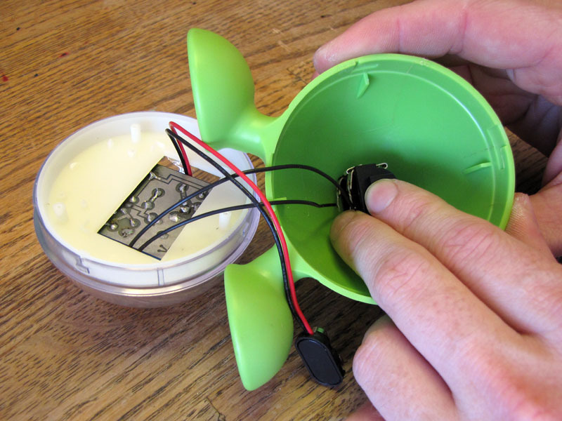
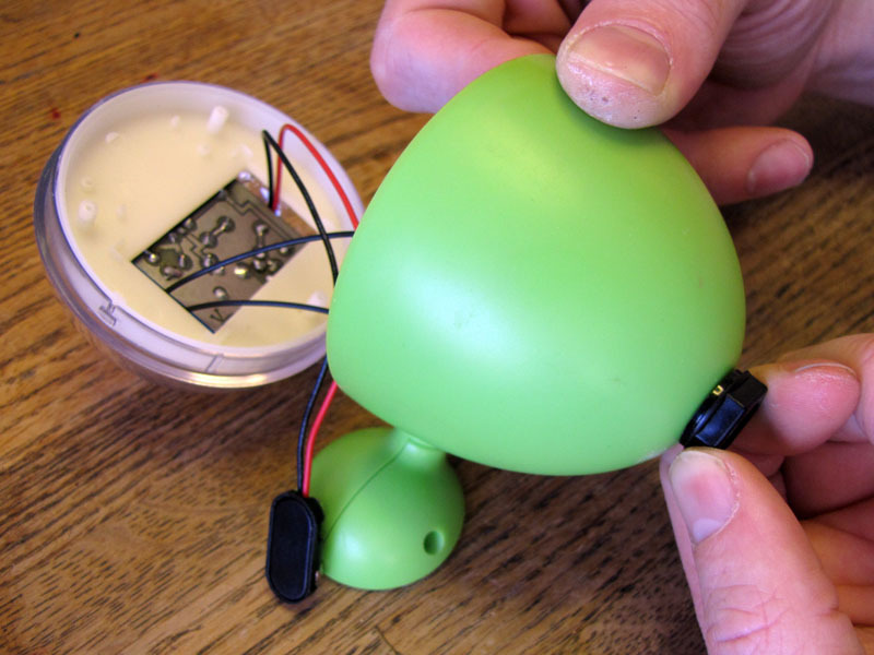
Disassemble your case.

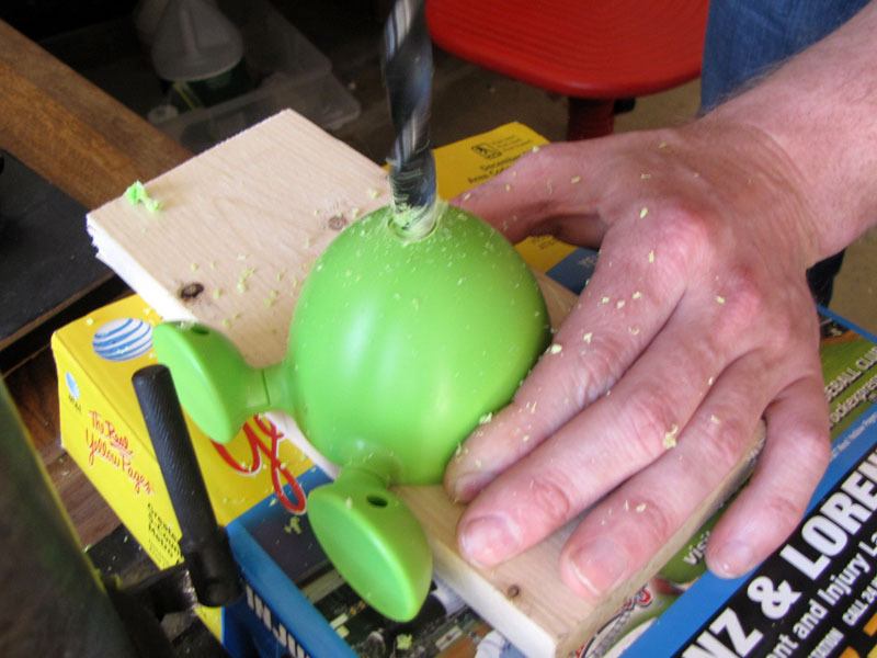
Mark and drill a 3/8″ hole, in an appropriate location, for the TRS jack.

At this time, you may also want to drill mounting holes for a power switch and/or a power jack, if you choose to use an external supply.

Prep jack

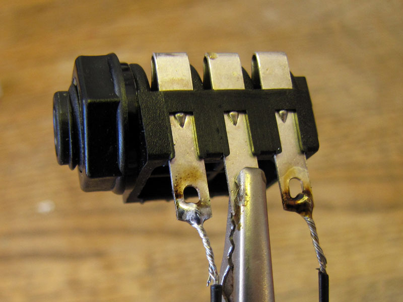
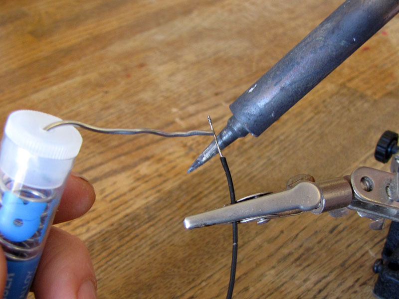
Strip about 1/2″ from each end of two 4″ pieces of 24 AWG hookup wire.

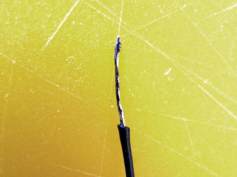
Tin the stripped ends.

Solder one end of one lead to the front leg of the 1/4″ TRS jack, and one end of the other lead to the back leg.

Form coil

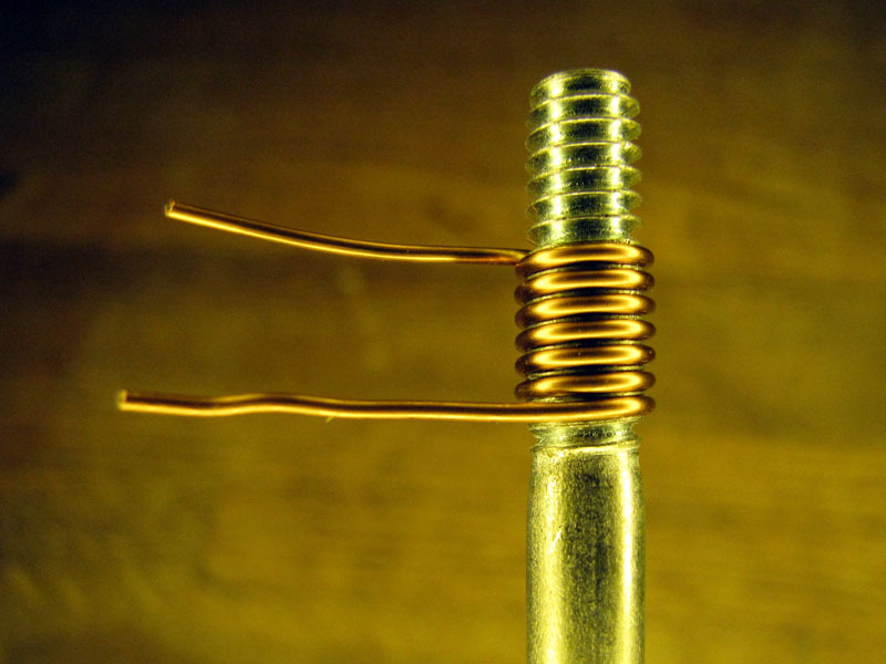
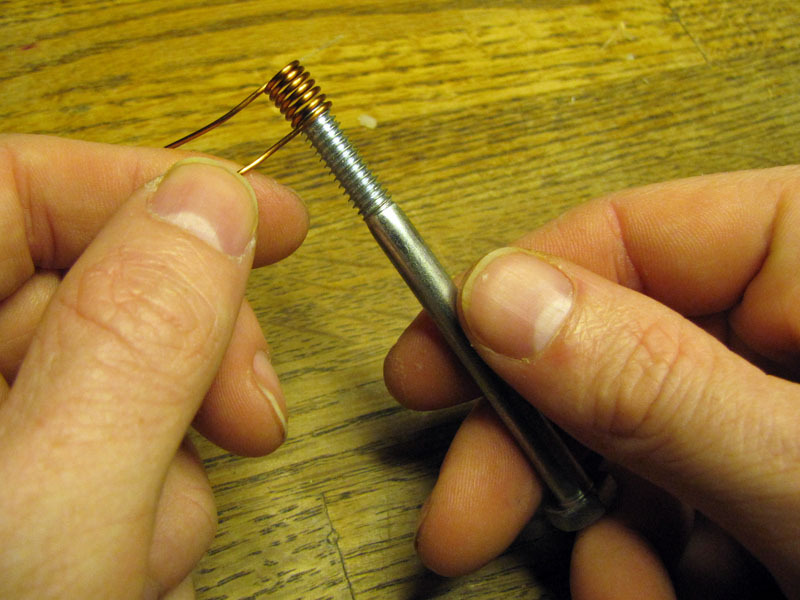
Take a piece of 19 AWG enameled copper wire, about 4″ long, and wind at least four turns about the threads of a 1/4-20 bolt or machine screw.

Rotate the bolt counterclockwise to unscrew the coil from the thread.

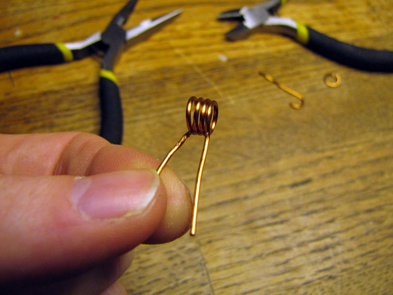
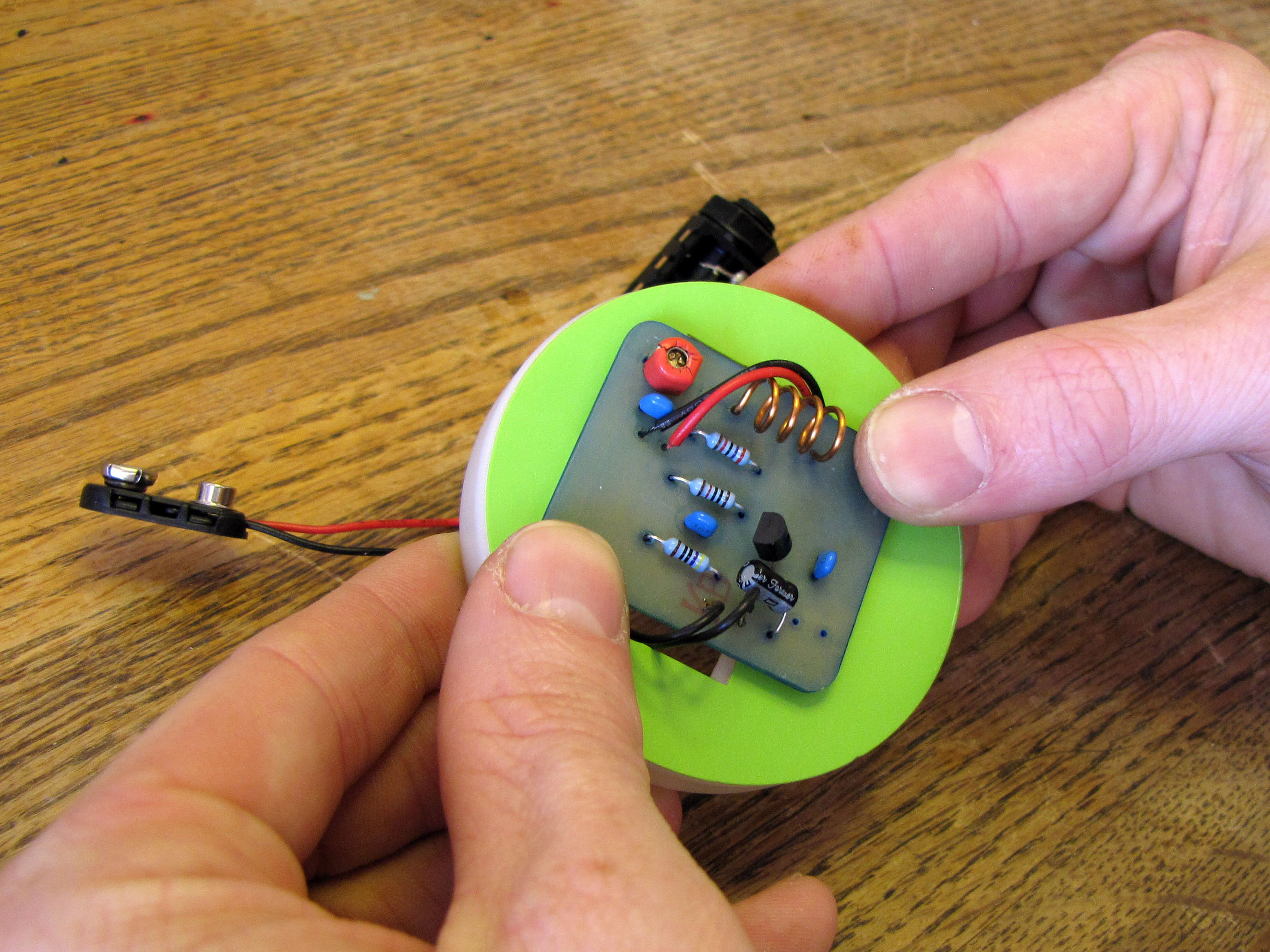
You want a total of four turns in the coil. Use small pliers to bend two legs down, as shown, and side-cutting pliers to clip them to about 1″ long.

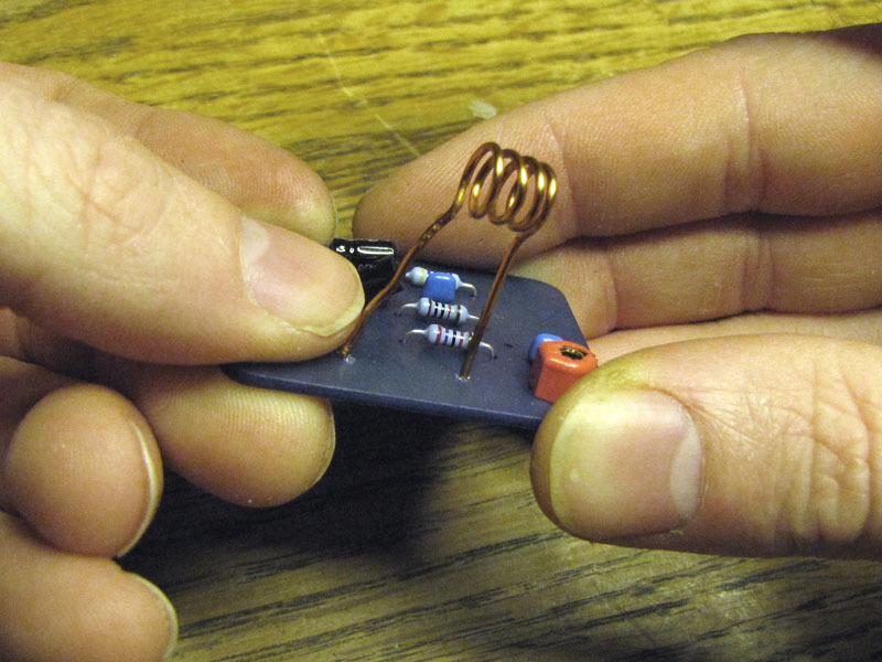
The mounting holes for the coil legs should be 12mm apart on the surface of the PCB. The act of installing the coil on the board should stretch it to the correct length, but you may have to tweak it a bit with pliers or a screwdriver to make sure the rate of coiling is even between the two legs.

Install components

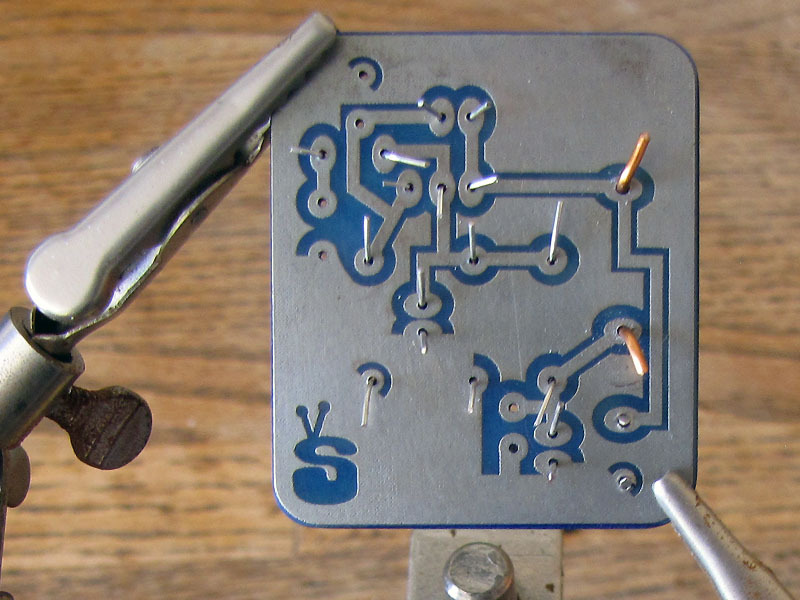
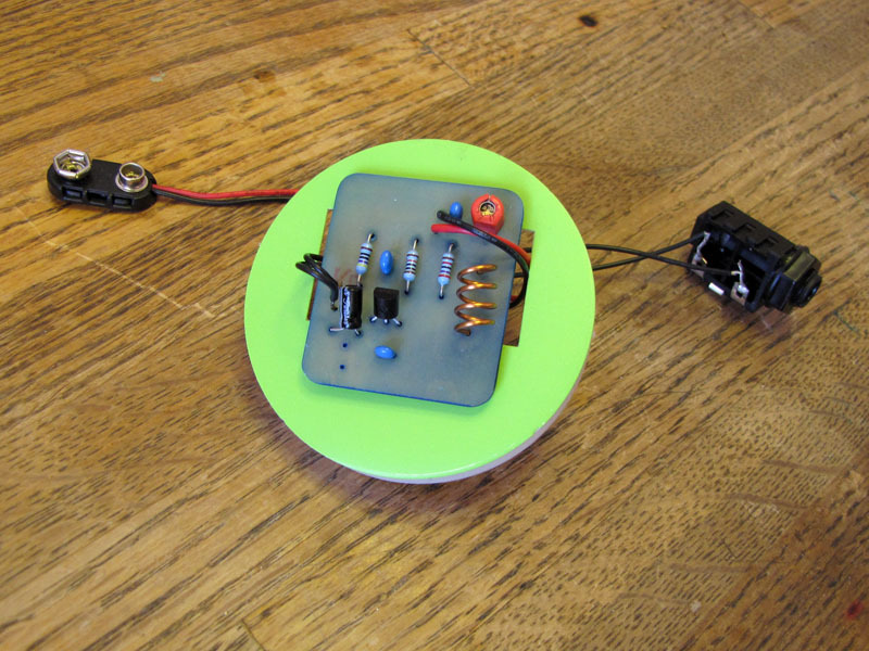
Bend and slip the component leads into the correct holes in the PCB.

Carefully note and verify the correct orientation of the electrolytic capacitor and wire leads.

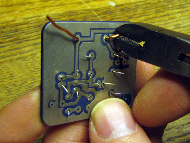
Bend the leads on the solder side of the board to temporarily secure the components in place. Clip them to about 1/4″ to open up a bit of room to solder in.

Solder components

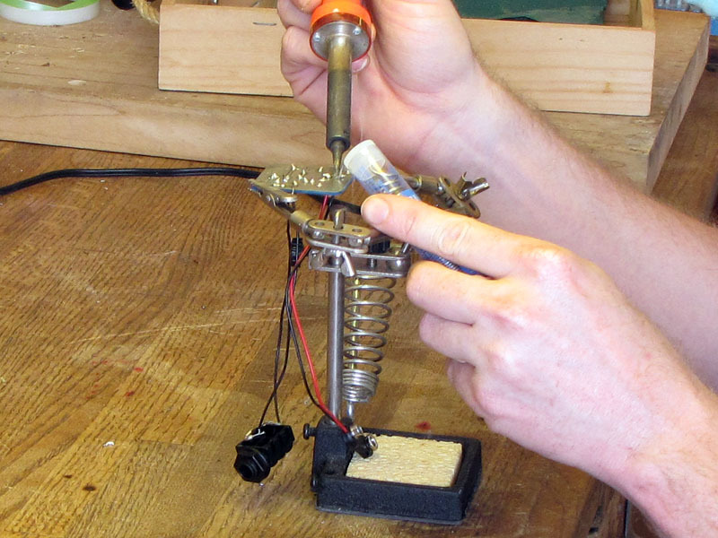
Clip the PCB, trace-side up, into your helping hands, or otherwise secure it, in a level horizontal orientation.

As always when soldering, be sure to work with plenty of ventilation and avoid inhaling fumes.

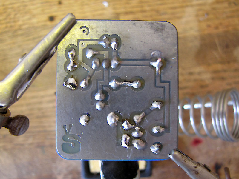
Flux, heat, and solder each lead in place.

Once the solder has cooled, clip any protruding leads with side or end-cutting pliers.

Mount PCB

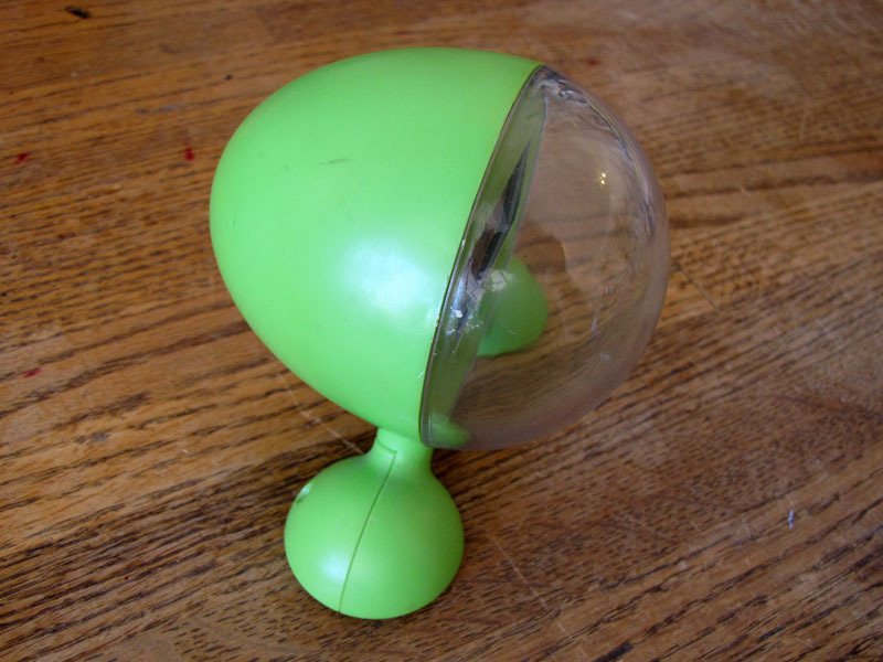
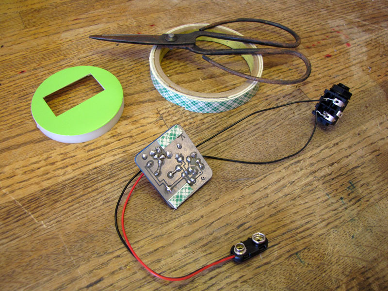
Mounting details will naturally vary with the case you choose. This foam-tape method worked great for my salvaged clock case, but your mileage may vary.

Attach a strip of double-sided foam tape to the featureless corners of the PCB, on the trace side, as shown. Each strip is about 1/4 x 3/4″.

Do not attach tape directly over the traces, or you may damage them if you ever have to remove the tape.

Remove the backing from the foam tape strips on the PCB.

Making sure the leads are first correctly positioned, carefully orient the PCB and press it into place.

Tune circuit

Connect a fresh 9V battery to the battery clip, and an audio signal to the TRS jack. I used the headphone jack of my laptop for an audio source.

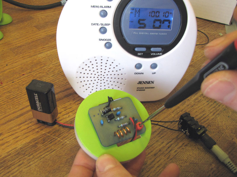
Turn on your FM radio, and scan around looking for your signal. I found mine at around 99.8 MHz. It may be quite static-y and noisy at first.

Use a small screwdriver to adjust the trim capacitor, as shown, until your signal comes through loud and clear.

Assemble

Remove the washer and nut from the phono jack and thread it, from inside the case, through the hole you drilled in Step 1.

Put the washer over the threads and tighten the nut down from outside the case, to secure the jack. Finger-tight is fine.

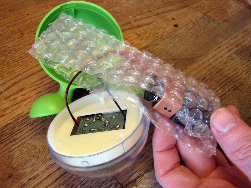
Attach a 9V battery to the clip, pad it with a scrap of bubble wrap, and stuff it in the case before sealing up.

I’m going to to modify my transmitter with a jack for an external regulated power supply. You may want to do the same, or at least add a power switch between the battery and the board. But for testing purposes, this set-up will suffice.

Use it!

Turn your radio on again, pick it up, and walk away from the bench ’til the signal fails. Mine was loud and clear to about 30 feet.

Depending on where you live, operating even a very short range FM transmitter like this, without a license, may conflict with applicable laws and/or regulations. Be sure to investigate carefully before turning it on, and err on the side of caution if in doubt.