Learn how to build the “persistence of vision” display, which is a classic DIY project with a computer chip that flashes LED lights super fast, as you swing the gadget through the air — making them appear like hundreds of lights displaying a message.
Projects from Make: Magazine
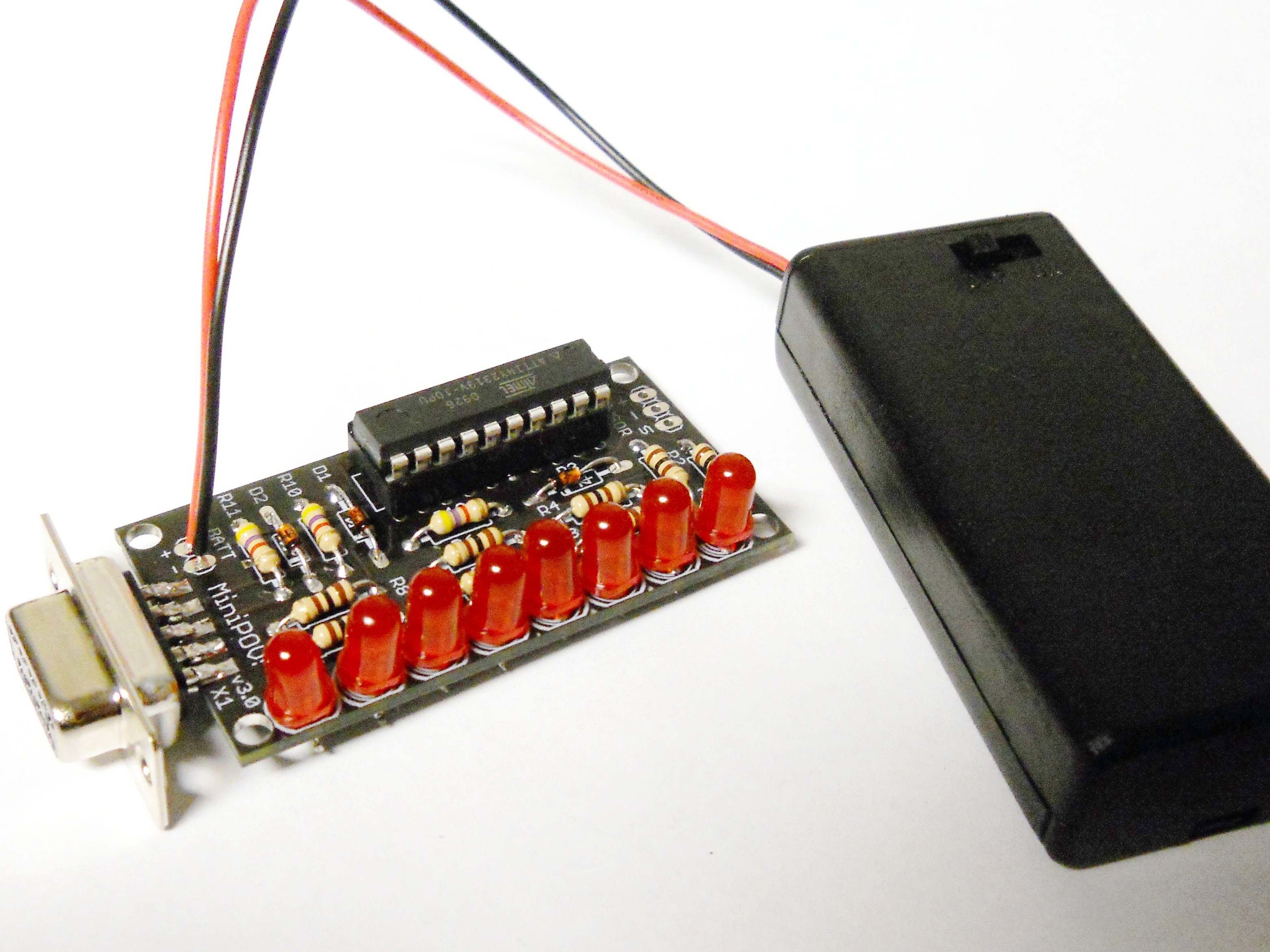
MiniPOV Kit
It's easy to assemble the Mini-POV kit; this guide walks you through the process step-by-step.