You may have seen those “On Air” lights at film, radio or television studios. Now that anyone can broadcast video over the internet, it’s time to learn how to build your own “Now Streaming” light that even wirelessly checks to see if you’re streaming!

This guide will show you how to:

  • Set up the XBee Internet Gateway
  • Connect your XBee to an Arduino to poll a web server for data
  • Use Ustream’s API to check if a channel is broadcasting
  • Use a relay to control an incandescent light fixture
  • Mount the light fixture a wood panel
YouTube player

Project Steps

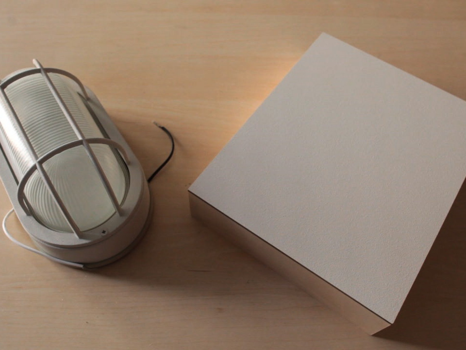
Mount the Light Fixture

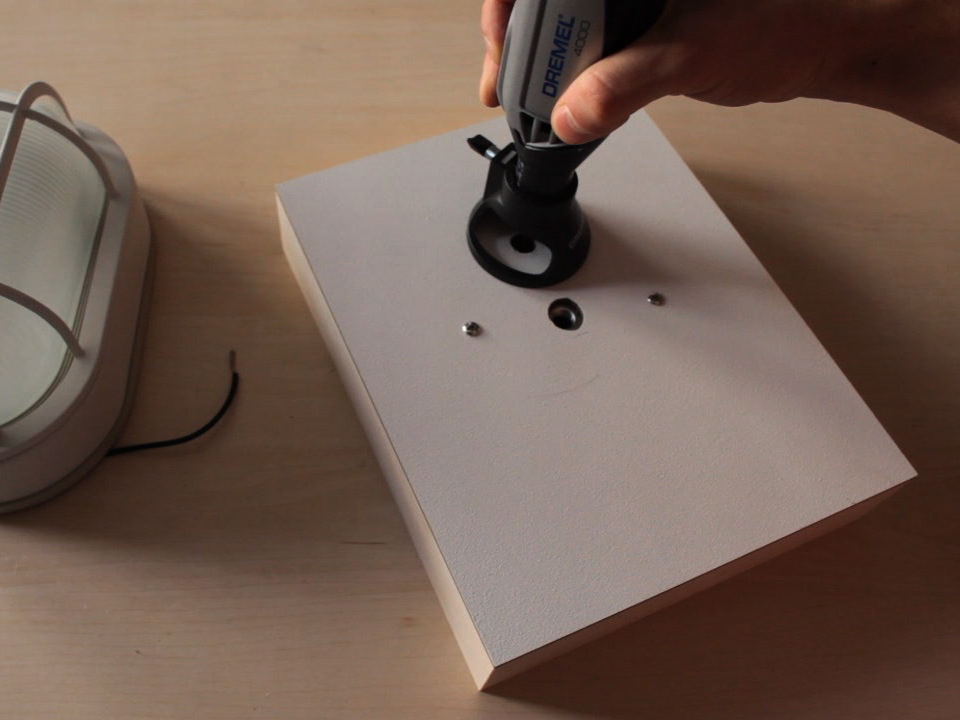
Using your rotary tool, cut a hole in the cradled panel for the light fixture’s wires and pull the wires through to the back.

Connect the Relay in Line with the Light Fixture

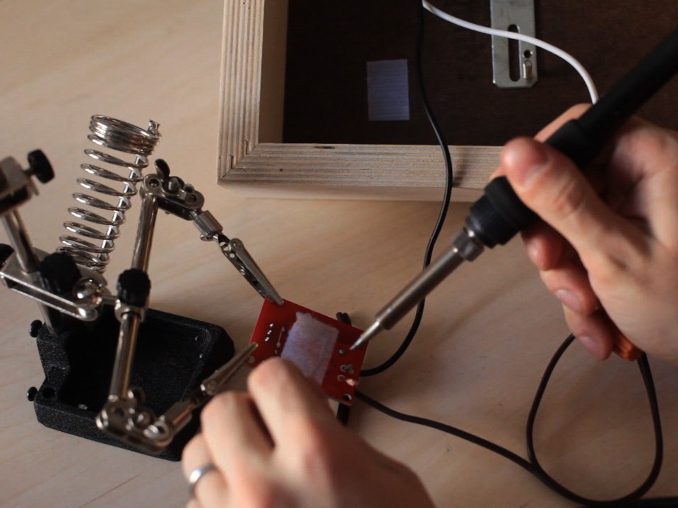
Solder one wire from the light fixture to the relay.

Cut the lamp cord to about 10 inches from the plug, split and trim the wires.

Connect one lamp cord wire to the relay and the other to the free lamp wire

Set Up the XBee Internet Gateway

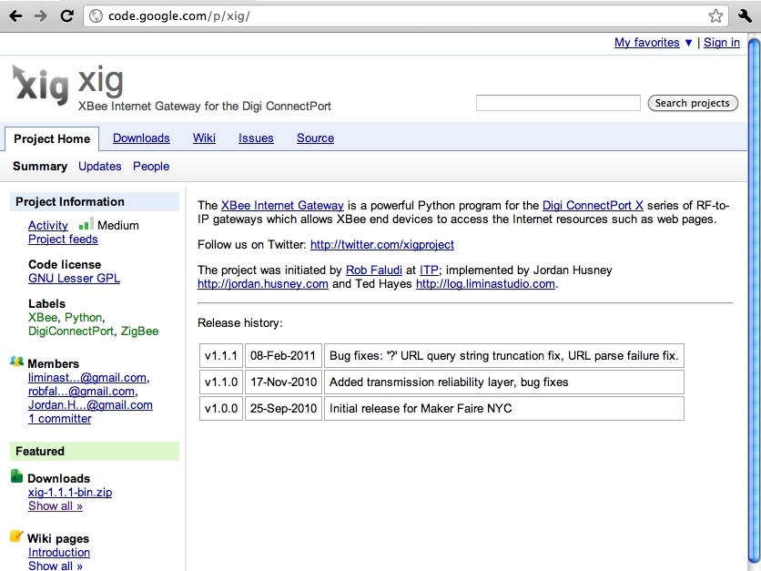
Download the XBee Internet Gateway software (https://code.google.com/p/xig/downloads/list).

Use an Ethernet cable to conenct the ConnectPort X2 to your router. Determine its IP address by using the software on the CD included with the ConnectPort or by checking your router’s log for the MAC address.

The ConnectPort X2’s MAC address is printed on the bottom of the unit.

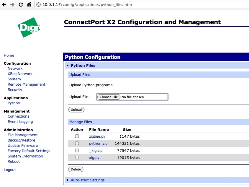
Enter the ConnectPort’s IP address into your web browser’s location bar.

Under the Python menu, upload the two XBee Internet Gateway files: xig.py and _xig.zip.

Click “Auto-start settings” and add xig.py and enable it. Apply those settings.

Under the Reboot menu, click “Reboot.”

Configure the XBee Radio

Attach the XBee to the USB adapter and launch a terminal program such as CoolTerm (http://freeware.the-meiers.org/).

Select the port that matches your USB adapter and select “Local echo” and click OK and then “Connect.”

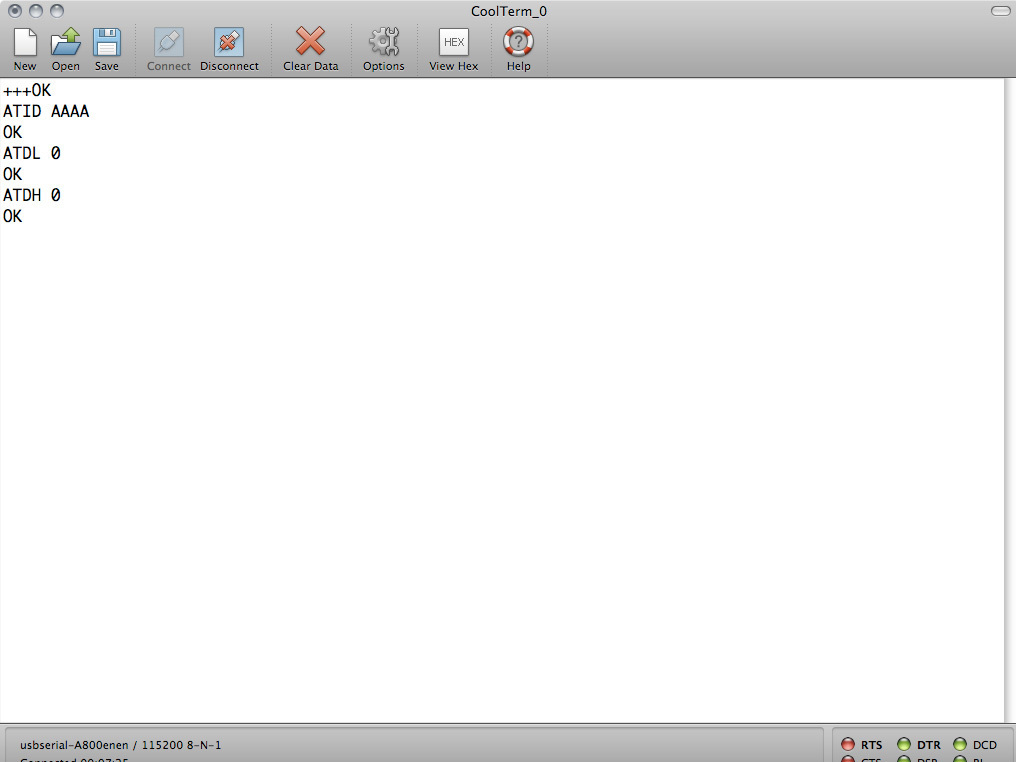
In the terminal window, type “+++” to enter command mode. The modem will respond “OK”

Command mode is active for 10 seconds after you type “+++” or hit enter after an AT command. If you take too long, type the plus signs again to go back into command mode.

Type ATID AAAA to set the PAN ID to match your gateway. The modem will respond “OK”.

Type ATDL 0 to set the low byte of the destination address to the ConnectPort X2, which is the coordinator of the network. Zigbee Network Coordinators always have the low address of 0. The modem will respond “OK”.

Type ATDH 0 to set the high byte of the destination address to the ConnectPort X2, which is the coordinator of the network. Zigbee Network Coordinators always have the high address of 0 The modem will respond “OK”.

Configure the XBee Radio, Continued

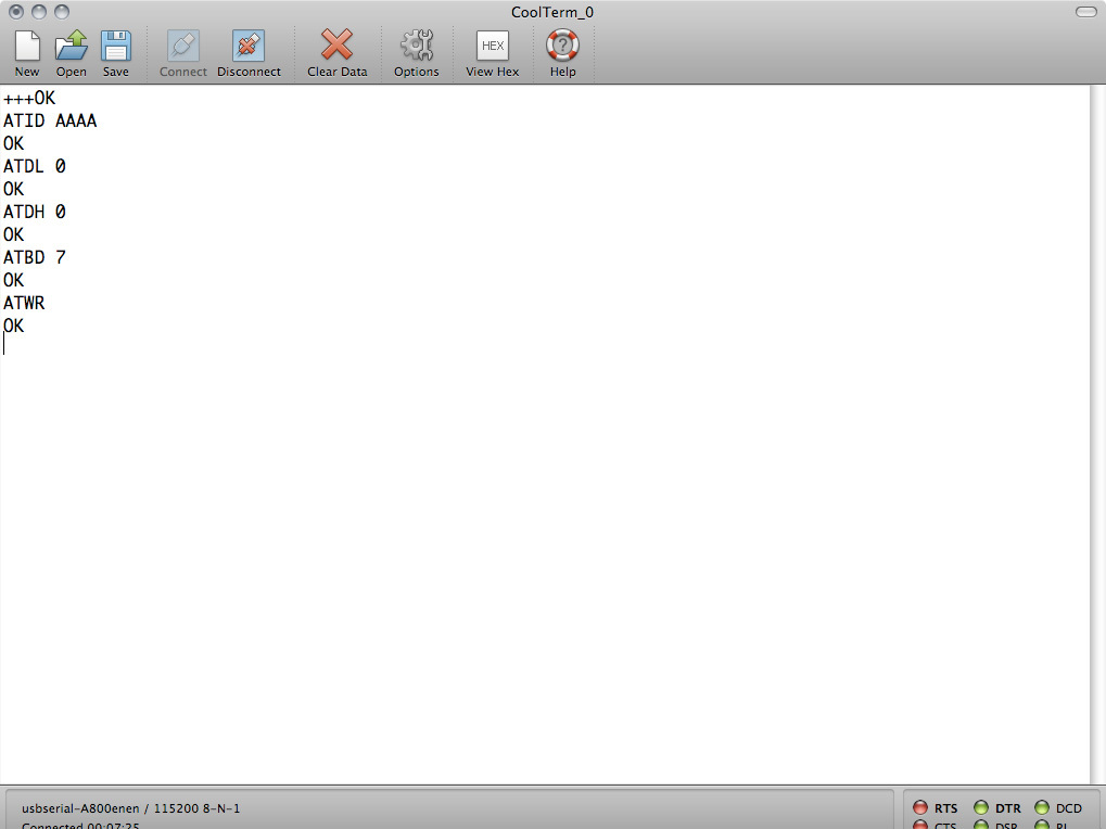
Type ATBD 7 and hit Enter to set the baud rate to 115200. The modem will respond “OK”.

You can check any of the settings by typing the command without the parameter.

When you’ve confirmed that the settings are correct, type ATWR to write the settings to the modem’s flash memory.

Disconnect and reconnect at 115200 baud.

Type help. The response should be information about the XBee Internet Gateway. If not, verify the ConenctPort and XBee settings.

Type in a web address such as http://www.google.com/ and hit Enter. If you see HTML, you’ve configured the XBee Internet Gateway correctly.

Set up the Arduino

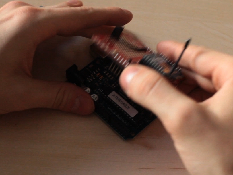
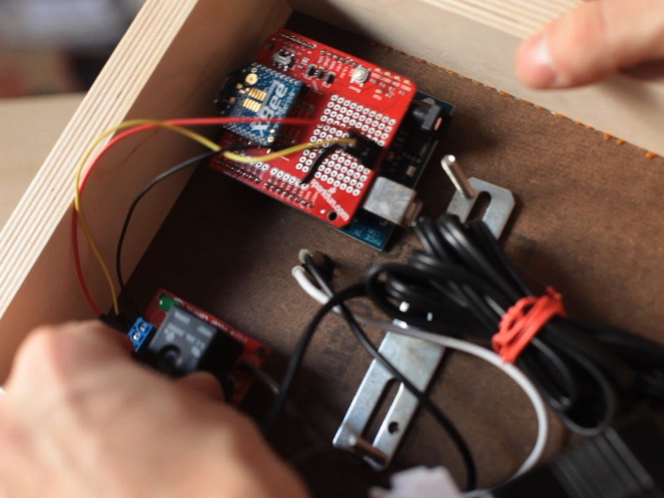
Insert the XBee into the XBee shield and put the XBee shield on the Arduino.

Upload the code (https://code.google.com/p/makezine/source/browse/trunk/arduino/on-air-light/on-air-light.pde).

Connect the Arduino to the relay board.

Using velcro, mount the components inside the panel.

Connect the power

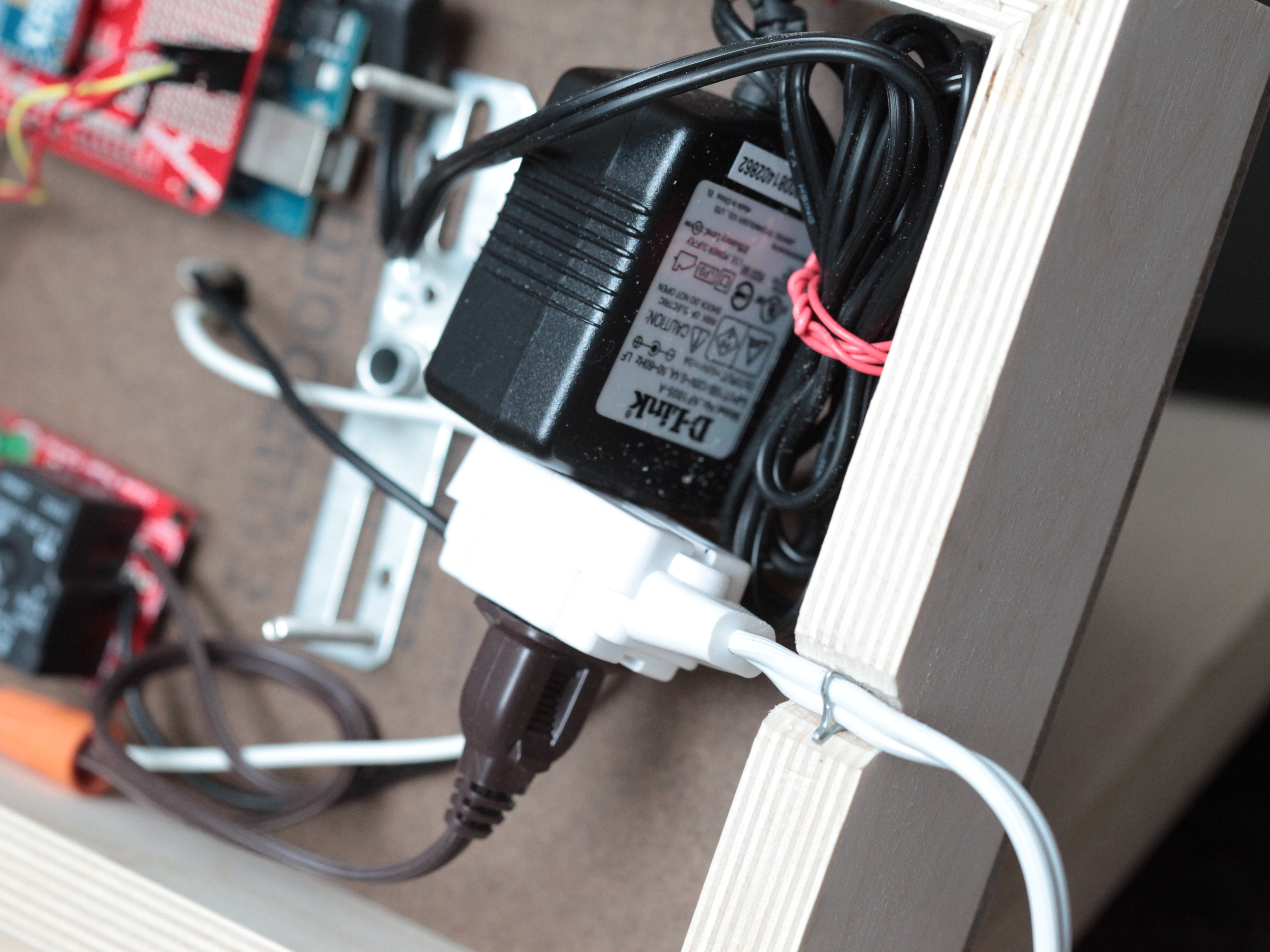
Connect the lamp cord and your 5V power adapter to the extension cord

Connect the power to your Arduino.

Create a notch in the bottom of the wood panel for the extension cord so that the panel can sit flush against the wall.

Finishing Touches

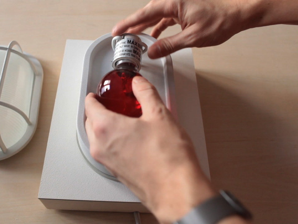
Insert red light bulb, replace glass fixture cover.

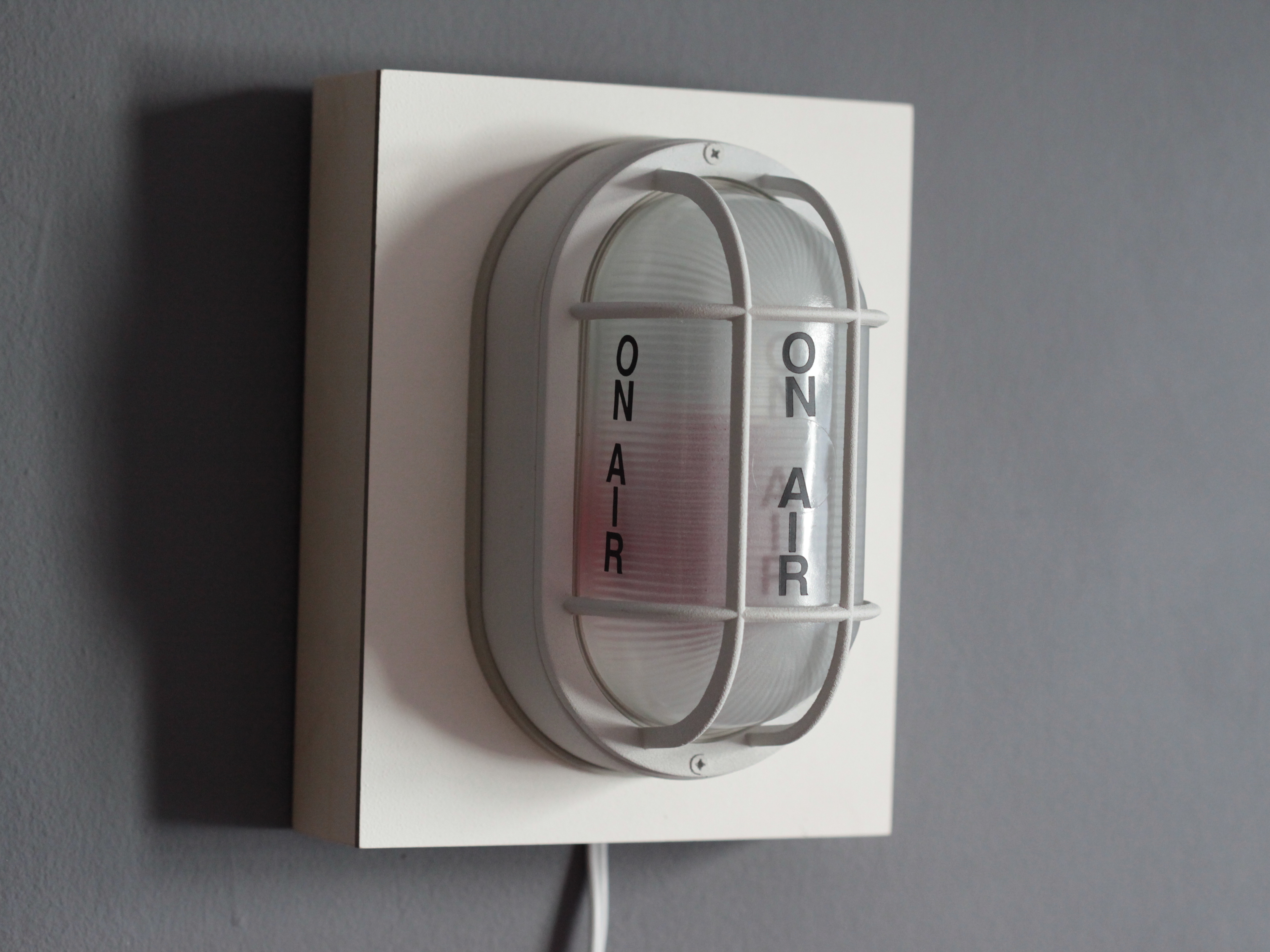
Use press-on letters to spell out “On Air” or whatever you want!

Add a hook to the back to mount the light on the wall.