RC hobby servomotors were just made for hacking. What’s not obvious is how much you can hack them — with a few tricks, you can use a servo to control almost anything.
Hobby servos consist of a DC gear motor, a potentiometer (usually 5K), and a control circuit. The output shaft is the output of the geared motor. The shaft also turns the pot, which returns a position-dependent voltage to the control circuit. When the servo receives a command to move to a new position, it runs its motor in the necessary direction until the pot indicates that the output shaft has reached the desired location.
What if you want motion more powerful or complex than a standard servo can give — can you do it? Certainly! Just replace the little motor with a bigger one (and whatever driver is needed) and/or replace the pot with one that senses the movement that you really want.
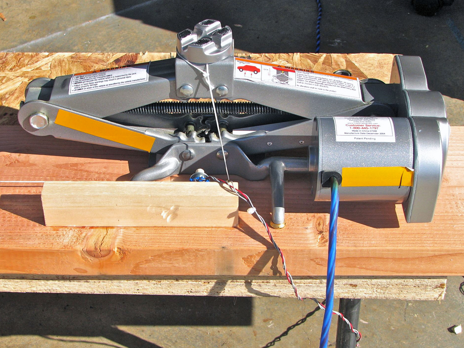
Let’s get started with extreme servo hacking. At Evil Mad Scientist Labs, we’ve modified a standard hobby servo to control an automotive jack. The result is a powerful, sub-$100 actuator that can move a heavy load with precise control, with a total stroke of 5"–10". It’s a powerful weapon in the maker’s arsenal for theatrical and Halloween props, CNC projects, and robotics applications.
Project Steps
Hack the jack.
We’ll start with a 1-ton, 12V automotive scissor jack. The controller has buttons labeled “up” and “down.” Open the controller to find the backside of the up button. With your continuity tester, find the 2 pins of the button that become connected when you press it.
Solder 2 long wires to those pins. Repeat for the down button, adding 2 more long wires across it.
Reassemble the controller. You may need to make a little notch for the wires to escape.
Get the servo to serve you.
Next, you need to eviscerate a servo. The best candidate is one with a bad motor, a broken case, stripped gears, or a bad pot. Unscrew and open the case to get at the printed circuit board (PCB). The appearance may vary tremendously, but the features shown in linear_servo_diagrams.pdf (in the documents section) are universal: an input (signal and power) cable, 2 outputs that go to the motor, and 3 wires that go to the pot.
Cut these latter 5 wires in half, carefully noting which 2 went to the motor and which one went to the middle (wiper) terminal of the pot. (Some servos have the motor and/or pot soldered directly to the PCB without wires. In that case, unsolder and remove the part(s) instead of cutting the wires.)
You’re replacing the servo’s internal single-turn pot with an external 10-turn pot. Solder 3 long wires — with a different color for the wiper — from the original pot’s contact tabs to the 10-turn pot, connecting wiper to wiper. (The wiper pin of a 10-turn pot is usually at the end opposite the shaft.)
To control the jack, you’ll use little relays driven by adjustable, single-transistor driver circuits. Begin by identifying which of the 3 wires on the servo’s control cable are power (+5V) and ground, and solder connections to those points.
Construct output driver #1 as shown in the linear servo pdf, watching the orientation of the capacitor (its negative side is marked), the transistor (its legs read E-B-C when you can read the writing), and the relay (its pin 1 is marked). Take either wire that previously went to the motor as the driver’s input, and connect the driver’s output to the 2 wires across the up button on the jack. An optional LED can be added for debugging.
Make an identical output driver #2 with the other motor wire, and connect its output across the down button.
Finish the feedback.
The jack’s movement must turn the pot in order for servo control to take place. Two working geometries are sketched in geometries.pdf in the documents section.
You can tie a string to the top of the jack, wrap the string one turn around the shaft of the pot, and then hang a weight below to maintain tension.
Or, a more general scheme is to wrap the string through a screw eye, around the pot, and then attach the other end through a rubber band (or spring) to a second screw eye.
For either method, the pot’s shaft needs some friction: wrap regular masking tape around the shaft 10 times, and then slide a ¼"-ID washer over the tape. This holds the tape in place and stops the string from rolling off the edge of the tape.
Get set, go!
Center both 500Ω trimpots in their ranges, and hook up your 12V source for the jack. Manually adjust the jack to middle height, move the 10-turn pot to mid-range, and then tension the string.
Turn on your servo control signal and see if it works. The jack’s movement should “lock up” wherever you want it to stop. If it doesn’t lock up — the jack moves to one end of its travel regardless of signal — then the feedback is backward. Fix it by swapping the 2 non-wiper wires going to your pot.
The 2 trimpots adjust the “dead band” of the servo; tune it between a loose lock, where precision is lower, and a too-tight lock, which may oscillate.
Conclusion
This project first appeared in MAKE Volume 18, page 123.