It seems that no matter how much things change, one thing that is always constant is a kid’s fascination with all things trains.

When my son was about 4 years old he was fascinated by passing trains. Even more captivating to him was the railroad crossing signals which would flash and ring to announce a train coming. Because he enjoyed it so much, I thought a small prototype of a crossing signal, perhaps one which could be placed in his playroom would be a lot of fun for him…and me!

My original prototype build turned out really nice, but it was quite difficult to build. Lots of mistakes, lots of time and lots of expense. But it was for my son, and well it was worth every hour and dollar I spent. Since that time however, there has been some interest in what I built as others have wanted to build something similar as well. So for that reason I thought I would try to make another. This time however I would document the process, make it simpler, and make it less expensive to build.

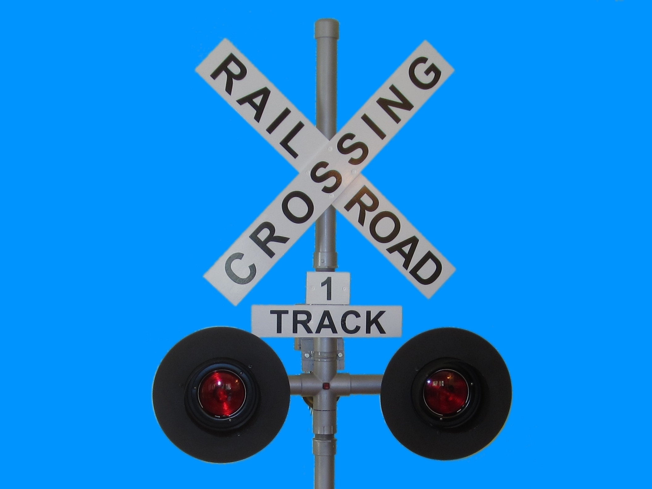
These instructions represent that effort. Here you will find my complete and detailed instructions on how to build a similar operating railroad grade crossing signal of your own. The crossing signal itself stands about 78″ tall, 31” wide and 28” deep. It features two automotive trailer lights for lamps, as well as an operating bell. Of course it also features the distinctive cross bucks which are recognizable on any prototype railroad crossing signal you may have seen.

Check out my blog post and video for a look at what came of this effort.

The operational features of this railroad crossing signal are described as follows;

  • Operating signal with operating lights (2) and bell.
  • Signal is activated by a push-button located on the signal mast.
  • Operates in two modes; 1) Time-out: Single press of button activates signal for 30 seconds then automatically shuts off 2) Continuous: Long press (hold down 2 seconds) activates signal until button is pressed again.
  • When activated, lights alternately flash approximately 2/3 second on, 2/3 second off.
  • Signal mast with realistic signs, lights, bell and controller is about 6-1/2-feet tall and about 2-1/2-feet wide.
  • Signal is painted in a prototypical way; gun-metal for mast, black and white for cross bucks, etc.
  • Constructed mainly from PVC as its structure and some hardwood for signs.
  • Constructed to be portable, as four easily separated and light weight sections.
  • Signal can be powered by commonly available 12V battery such as a lawn, tractor or motorcycle battery or suitable wall adapter (~3A to 5A works best).
  • Can be easily adapted to being activated by a wireless remote (if desired). For more details on that modification see Got Wireless? Modify a Simple 12VDC Wireless Remote Control for 5VDC Operation

The build is also very light and portable (built from four main sections which can be easily separated). It is primarily made from PVC pipe as its main structure which also makes it light weight. The signal can be easily assembled and disassembled in about 5 minutes making it ideal for train shows, club spaces and / or demonstrations of all kinds.

If you have interest in having an operating signal like this (similar to a stage prop) I hope you find these build instructions useful. I also hope you have as much fun building (and modifying it your own way) as I did making (and re-making) it. Enjoy!

Project Steps

Overview

This signal is built from four (4) major subsections. By breaking this project into four subsections the overall design and construction is greatly simplified. It also helps make this project easily modified by simply swapping out or replacing one of the sections with another.

The four main sections are; The H-Base, Rise Pole, Middle Mast (with signals, bell, and controller), and the Top Mast (cross bucks).

These instructions will cover construction of each of these four subsections.

We will start with the “middle mast” first since it is the most interesting, however it is also the most complex.

Overview – Middle Mast

We start these instructions by first building the middle-mast. This subsection is first because it is the most interesting (when finished it operates!) but also the most complex. Once the middle mast is complete the remaining three subsections are quite straightforward.

The photo accompanying this step shows an overview of the PVC sections which make up the middle mast.

Note: You can see from the photo, the 1-1/2” threaded connector on the top and bottom provide an easy attachment point for the riser-pole and base at the bottom and the top-mast (cross bucks) at the top. All one needs to do is screw these sections together.

Gather PVC Fittings

To build the middle mast you will need the following nine (9) fittings;

One (1) 1-1/2” 4-Way Coupler(Cross) – Part-H

One (1) 3-Way 1-1/2″-1-1/2″-1″ – Part L

Two (2) 1-1/2” 90-deg Elbow – Part J

Four (4) Female 1-1/2” Adapters (threaded) – Part E

One (1) 3/4″x1″ Male Adapter (threaded) – Part O

Cut PVC Pipes To Length

Cut eight (8) PVC pieces as described below.

Two (2) 8” 1-1/2” PVC (Part-I)

Two (2) 3” 1-1/2” PVC (Part-K)

Three (3) 2” 1-1/2” PVC (Part-D)

One (1) 2” 1” PVC (Part-N)

Test Fit the Middle Mast

Assemble the nine PVC connectors and eight cut pieces as shown in the photo.

Press fit assemble all middle mast pieces as shown.

Don’t glue anything until you know everything is how you like it.

All pieces should look symmetric and tightly fit together.

Take care to make sure there is enough gap between the top of the 4-way fitting and the bottom of the 3-way fitting to accommodate the 1-1/2″ galvanized pipe hanger. This hanger is used to mount the bell.

Take care to make sure there is enough gap between the top of the 3-way fitting and the bottom of the top 1-1/2″ female threaded fitting to accommodate the 1-1/2″ galvanized pipe hanger. This hanger is used to mount the track signs.

Check that all parts which should be perpendicular are so. This includes the 90-deg elbows and the 3-way connector with respect to the main mast center line.

Make tick marks with a Sharpie to note each piece’s orientation for later when these pieces are glued up.

Attach Electrical Box

Locate the middle 3/4” hole on the back of the 5 hole electrical box. It is a threaded hole usually used for rigid conduit connectors.

Attach the all-weather 2-gang outlet box by threading it onto the 3/4″ male thread on the back of the mast.

Tighten box on the threaded fitting, but not too tight or else it might snap off.

Drill Holes for Lamp and Bell Wires and Push-button

Now disassemble the middle part of the mast from the arms with the 90-deg elbows. This is Part-E, D and J.

Glue the 2″ length pieces which attach the threaded fittings to the 90-deg elbow. This is the only part which will be glued at this time.

When gluing PVC parts, always first apply purple primer, then PVC cement. Work quickly as the setting time is very fast.

Drill 3/16″ holes in the bottom of each of the 90-degree elbow sections. This is where the wires for each signal light will exit the assembly.

Replace the fitting onto the middle-mast assembly again. Repeat for both arms.

Drill 3/16″ holes in the bottom of the 1” section which goes into the 3/4” male threaded fitting. This is where the wires for the bell will exit the mast assembly.

Lastly drill a 1/2″ hole in the front of the 4-way connector to mount the push-button switch. Don’t drill the entire 1/2″ all at once. First drill a pilot hole at approximately 1/8″, work up to 1/4″ and then the full 1/2″.

Wire-up Mast

Now you will understand why very little has been glued together at this point. It will make wiring up the mast much easier.

Use 18AWG wire throughout the assembly. Automotive or speaker wire is usually very durable and suitable for this application.

It is often very helpful to use wire which has one of the conductors uniquely identified, such as a white stripe, silver vs. copper colored wire, or other markings.

Labeling all wires is also essential.

Wire Signal Lamps

First start with the signal light wiring. Recall that you will be wiring two signal lamps.

Wires should go into the arm pipe from each elbow end and up the 4-way fitting into the electrical box. Leave about 8″ coming out of the box.

At the end of the signal arm, tie a knot about 4″ from where the wire leaves the pipe into the 90-deg elbow. This will serve the purpose of a strain relief.

Thread the wire end down through the 3/16″ hole drilled earlier. Leave about 6″ of wire remaining protruding from the hole.

Strip and crimp a red (16-22 AWG) male terminal to the wire which will be used for the signal output (will be connected to the lamp BLACK or COMMON wire). This is the one which will be bolted to the signal housing.

Strip and crimp a red (16-22AWG) female terminal to the other connector which will go to either the RED or BROWN wire on the signal lamp.

Both conductors (a pair) should extend from the end of the signal arm (at the elbow).

Do the same with the other signal arm. Be sure to label the connections (LEFT SIGNAL, RIGHT SIGNAL) inside the electrical box.

Wire Push-Button

Next run the wire for the push-button trigger which will go through the 1/2″ hole on the front of the 4-way fitting.

Route this wire pair through the front of the 4-way and back into the electrical box from behind. Leave about 8″ again at both ends.

Again be sure to label the connection (SWITCH) inside the electrical box.

At this point you will have both SIGNAL wires (2-pairs) and the SWITCH wires (1 pair) inside the electrical box.

Wire The Bell

Run the wire pair for the bell which will go into the 1” PVC pipe (attached to the electrical box) through the 3/16” hole drilled underneath it earlier.

Route the wire up into the PVC pipe and out the electrical box from behind. Leave about 8” again at both ends.

On the end which hangs down from the PVC pipe, strip and crimp a forked red terminal connector to each of the two wires in the pair. These will be used to screw to the bell when it is attached.

Be sure to label this connection (BELL) inside the electrical box.

At this point you will have four pairs of wires inside the electrical box. One pair for the BELL, one pair for the SWITCH and two pair for the SIGNALs.

Attach Molex Connector

Now bundle the 8 signal wires (4 pairs) at the PVC pipe entrance inside the electrical box and secure them with a wire tie.

Strip, crimp and assemble the 8 signal wires into the 8-pin Molex female connector. Be sure to connect the V+ common wire from the Molex connector (pins 2, 4, and 6) to the SIGNAL and BELL wires which will go to common or chassis on the lamps and bell.

The other conductors will go to the individual lamp1, lamp2 and bell signals (pins 1, 3, and 5).

Polarity on the push-button SWITCH does not matter.

Prepare Electrical Box Hole Plugs

There are two 3/4″ holes at the top and bottom of the electrical box. You can insert the 3/4″ plugs into the top two holes and one of the bottom holes.

The 4th one will be for the power cord which will be drilled to allow the power cord to pass through into the box.

Drill a 5/16″ hole into one of the electrical box plug inserts. Clean out by filing or grinding with a Dremel Tool the side slots just enough to allow for clearance of the rubber grommet when inserted into the drilled hole.

File the edges removing any sharp edges.

Install a 1/4″ rubber grommet into the hole.

Wire Power Cord

Run the power cord wire through the grommet. This wire may be of a heavier gauge, from possibly a common household extension cord with the ends cut off.

Wire it with about 8″ inside the box (with a strain relief knot) but leave about 4-feet extending below the box (or however long you need it).

Strip, crimp and assemble the 2 conductor power cable wires into the 2-pin Molex female connector. Be sure to observe proper polarity (i.e. black or striped wire to ground, other wire (red or unmarked) to +12V).

Attach cigarette lighter adapter connector to the other end of the power cable. Again, observe proper polarity. Typically the outside of a cigarette lighter is ground while the tip or point is +12V.

Note: In this build I used a CLA (Cigarette Lighter Adapter) for the power connection. Clearly it is possible to use your favorite power connector here. Feel free to modify the design to suit your needs.

Attach the Push-Button Switch

Pull the push button trigger switch wire back through the 1/2″ hole in the front of the 4-way fitting and slip on the toggle switch nut.

Re-thread the wire through the 1/2″ hole. Strip apart the wire and slide on a 1″ piece of 3/32″ diameter heat shrink tubing onto each of the two conductors.

Solder on the push-button trigger switch.

Let it cool and slide up the heat shrink tubing to cover the soldered connections.

Shrink the tubing with a heat gun, hair dryer or worst case the edge of a soldering iron.

Once the connections cool, insert the switch into the 1/2″ hole and tighten the nut to the switch body.

Test Mast Wiring

At this point the rough wiring for the mast is complete.

Both signal lamps, the bell wire, push-button switch and power have all been run.

Double check your connections and labeling using a continuity meter at each end of each of the 5-pairs of wires (10 connections total).

Track down and fix any wiring errors.

Drill PCB Holes in Electrical Box Cover.

Now it is time to attach the electrical box cover, but first we will use the cover to mount the controller PCB.

You could use the controller I designed specifically for this project or one of your own.

If you decide to use the one I designed, use an unpopulated PCB or print out the PCB mounting template to use as a guide (PDF).

Align PCB/template on the inside of the wall outlet cover with masking tape.

Align PCB to either the right or left as to allow room for the connectors and wires to extend out from the PCB and into the PVC tube.

Drill 4 holes 3/32″ diameter to match the standoff mounting holes on the PCB.

Countersink Holes and Attach PCB

Flip wall outlet cover and counter sink holes for a flange #4-40 1/2″ screw.

Insert the #4-40-1/2″ screws and secure them to the box cover with #4-40 nuts (4).

Align PCB mounting holes over 4 screws with nuts retaining those screws to the box cover.

Secure PCB to electrical box cover with #4-40 nuts(4).

Building the Controller

The Railroad Grade Crossing Signal Controller is built from a custom PCB I designed.

It is a small through-hole PCB with a minimal amount of components which provide the signaling control for the button, lamps and bell.

I have published as Open Source all of my PCB designs, build instructions, and software on Google Code.

You can find the entire controller project at this location by clicking here.

Additionally, you can view a guide which describes how to build the controller step-by-step. Railroad Grade Crossing Signal Controller

Alternatively you can certainly use your own controller design as well. Many people prefer using a development board such as the Arduino for projects like these. Arduino would be a really great alternative.

Test Wiring with Controller

Now we have enough built where we can test the controller and our wiring.

Connect the controller 8-pin Molex cable with the signal wires.

Connect the controller 2-pin Molex power cable.

Attach a 12VDC power supply to the power cord. This may be either through a CLA, wall power supply or something else. As long as the power supply is about 12VDC @ 3A you should be in good shape.

With everything connected and powered on, the PCB controller should show a single green LED light on. This is the power light from the on board 5VDC regulator.

Now press the button. You should see two red LED lights toggle and one red LED momentarily flash in time with the others. The momentary flash is used to hit the bell with a quick pulse. The other two LEDs are used to indicate the signal lamp state.

Press the button again cancel the signal and the LEDs should turn off.

Press again and release. This time wait 30-seconds. The LEDs should turn off by themselves. Here is a video showing how this operates.

Close up the Controller Box

At this point, with the controller tested, you can now close up the box.

Place the electrical box cover back onto the electrical box with the PCB inside the box.

Use 4 machine screws provided with the cover to secure the cover to the box.

Everything should fit nice and snug.

Glue

Now it is time to complete the glue up of the middle mast section now that we know all the parts fit properly and the wiring is finished.

Start first with the signal arms and work your way inward. Then work from the bottom up.

Use purple primer on both surfaces to be joined. Quickly apply cement and make the joint.

Be careful to quickly line up the pieces as the cement hardens very fast.

To help in the alignment process, during test fitting use a Sharpie to mark tick lines on the two pieces to be joined. This will help you line up those pieces quickly once the cement is applied.

Cement all pieces until the center mast is completely glued.

Hold off on painting the mast right now. It’s best to construct the entire signal first, then go back and paint.

Signal Lights

The following steps describe how to construct the signal lights. You need to make two of them, so just repeat these steps for the second light as well.

The most difficult thing to work out is probably the signal lamps. Based on your own selected tail lamps, construction and mounting may be different and may require unique solutions to work properly in your particular situation. Here is how I did it.

First, disassemble the tail lamp including the lens, retaining ring, gaskets and bulb.

Look over the assembly and study what you have. Decide if the mounting procedure I described here is suitable or if something else needs to be worked out.

Construct Signal Light Mount

With the signal light disassembled, locate the center point of the lamp housing. Mark it with an awl.

Use the circle template (see attached PDF file rrxing_circle_guide.pdf) to locate the 3 holes 120-deg apart approximately 3/4″ from the center hole.

Drill out all 4 holes with a 1/8″ drill bit. Use a backing block of wood for support while drilling into the steel to keep the holes clean.

Do the same to locate the center of the 1-1/2″ threaded plug. It should be a 3/4″ radius. Again mark the location with an awl.

Pre-drill a 1/8″ hole in the center of the threaded-plug.

Attach Signal Light Mount

Attach the PVC 1-1/2” threaded-plug (Part-P) onto the steel taillight housing with a #8-32 1/2″ sheet metal screw (with a hex flanged head).

Once attached, pre-drill (1/8″) the other 3 holes through the steel and into the PVC threaded-plug.

Attach three more #8-32 1/2″ sheet metal screws.

The housing should be securely mounted to the plug now.

Prepare the Sun Blocker Lamp Mounting Holes

Separate the 4″ wall thimble (used for home exhaust ventilation) into two parts. One will be slightly smaller in diameter than the other, but this will not be noticeable when mounted on the mast as sun blockers.

Place the taillight housing into the one-half of the wall thimble to locate the place where the three screw holes will be.

Take care to locate the bottom screw hole adjacent to the flange of the housing around the wall thimble.

Carefully center the housing and mark with an awl.

Pre-drill a 5/32″ pilot hole at each of the three locations to accommodate a #8 machine screw. You can use the circle template (see attached PDF file rrxing_circle_guide.pdf) again to help you center the housing and wall thimble together.

Prepare the Sun Blocker Disc Mounting Holes

Using the circle template (see attached PDF file rrxing_circle_guide.pdf), locate the position of three more holes around the outer rim which will be used to mount the 12″ signal light discs around it.

Again mark locations with an awl and pre-drill three 3/16″ pilot holes which will accommodate the 1/2″ #8-32 machine screws. Construction of the discs will come later.

Use the circle template to locate the thimble’s center point (using the 4-1/2″ diameter ring). Place holes at 3-3/4″ radius in three evenly spaced places (120-deg apart).

Now attach the signal light assembly inside the wall thimble. Align three screw holes and use three #8-32 3/8″ machine screws and three #8-32 lock-nuts.

No need to tighten completely because we will eventually remove this before making the sun blocker discs (optional) and painting.

Wire Signal Lamp Connections

Now complete the wiring terminals for the signal lamps.

The signal lamps have two wires (red-dim and brown-bright, other colors are possible).

You will also need a grounding signal wire which will be connected to the signal light housing. There will typically already be a hole available for inserting a #8-32 machine screw into the housing for a ground signal wire.

Now cut an approximate 6″ length of 18AWG minimum wire (preferably black or other color than the other two wires).

Use a red (22-16 AWG) ring terminal and crimp it to one end of the wire.

Crimp a red (22-16 AWG) female connector to the other end of the wire.

Attach the ring terminal to the light housing using a #8-32 1/2″ machine screw. This wire is the signal wire which is turned on to make the light turn on. The signal is turned on when this wire is grounded.

Finish off the red and brown leads by crimping a red (22-16 AWG) male connector to the ends of these wires as well.

Attach Signal Lamps to the Middle Mast

After performing the previous series of steps twice, once for each lamp, you now have two completed signal lamp assemblies.

Attach the lamps to the middle mast by simply screwing them into each of the extension arms on the mast. Only a few turns are necessary.

Thread them on such that they are secure onto the mast, but also leave the wire connections toward the bottom.

Attach the wire terminals from each lamp to the wires from the controller.

Connect the signal wires to the lamps using the crimp terminals installed earlier. The +V or common line should go to either the red or brown wires depending on the brightness you desire. The other line should go to the chassis or black wire.

Reassemble tail light replacing the bulb, lens and retaining ring. Do the same as above with the other signal light as well.

Go ahead and apply power again to the controller and trigger the signal. The lamps should flash just as the indicator LEDs did earlier. If not, try to examine the connections and trace out where the problems might be (i.e. burnt out bulb?).

Your signal now has operating lamps!

Prepare Bell

You must modify the bell as provided slightly to make it work as we need it to in this project. The bell that is provided is a make-break continuous operating bell. We need to convert this to a single strike bell. The modification is very simple.

Drill a 1/16″ hole into the terminal without an existing screw (YELLOW).

Insert a small wire between this hole and the chassis terminal screw (BLUE).

Solder one end of the wire to the hole you drilled. This effectively creates a short in the bell circuit to not allow the connection to break when the bell is energized allowing for single strike operation as provided by the electronic controller.

Remove the wire punch out from the bell chassis to allow wiring while the bell cover is on.

At this point we have not made the mount for the bell, so just connect the bell using the crimp terminals for now. Let the bell hang there gently.

Finishing the Middle Mast (Almost!)

At this point things are beginning to shape up. But we still have a few things to do to finish up the middle mast.

To complete the middle mast we still need to attach a mounting block for the bell (Part-G) as well as the track signs Part-F (e.g. “1 Track”, “2 Tracks”, etc.).

The following steps will guide you through constructing the mounting blocks needed to attach these components.

We will however make 3 mounting blocks at the same time. This is simply because it is just easier to make all the mounting blocks at the same time.

We will make one for the bell, one for the track signs and finally one for the cross bucks themselves.

To start this, cut an approximately 14″ long piece of 1/2″ stock (may be plywood, oak, etc.) 4″ wide.

From this piece will be the the 4″ block (Part-E), a 6″ block (Part-F) and a 3″ block (Part-G).

Refer to the PDF file included with these instructions (rrxing_signs_and_mounts.pdf)

Mounting Block Risers (for Parts F and G)

Part-F (track sign mount) and Part-G (bell mount) need to be raised slightly from the mount on the mast to accommodate the extra 1/4″ rise above the pipe that the PVC couplings take up.

Notice how a flat surface lays against the pipe with the raised coupling thickness. Compensating for this gap makes the mount a bit more solid and looks more finished.

This can be made by attaching a scrap 1″ x 3″ strip of 3/16″ material (hardboard, or plywood) along the center of both parts.

Another way, if you have access to a router, is to rout a 1″ wide channel down the center of the block 5/16″ deep. A 1/2″ thick strip of material can be placed in the gap creating a 3/16” riser so the mounting block sits flush against the pipe fittings.

You can choose which method works best for you.

Mounting Blocks (Drilling Holes and Inserts)

Mark locations for pilot holes and mounting holes (threaded inserts) which will be inserted in mounting blocks F and G.

Drill each pilot hole, indicated on the drawing (rrxing_signs_and_mounts.pdf) as a solid black and open hole) with a 1/8″ drill bit, there are 8 of them.

Drill each threaded insert hole (marked on the drawing with an open hole) with a 5/16″ drill bit, there are 4 of them in total. Two on Part-F and two on Part-G.

The wood inserts on Parts-F and G need a 5/16″ hole and the inserts can be screwed in with a hex wrench.

Mounting Blocks (Drilling Holes and Inserts)

Mark locations for pilot holes and mounting holes (for T-nuts) which will be inserted in mounting block Part-E.

Drill each pilot hole (marked on drawing as a solid black and open hole) with a 1/8″ drill bit, there are 6 of them.

The T-nuts (two of them for Part-E) need an outside diameter of 7/8″ drilled with a forstner or spade bit, approximately 1/8″ deep.

The center for the two T-nuts should be drilled out with a 3/8″ bit as a through hole.

Insert 2 T-nuts into each of the bored holes and press or force fit each T-nut using a hammer.

Place Mounts on Mast

With the 3 mounting blocks now constructed, it is time to place two of them on the mast. We will leave the cross buck mount for later (Part E).

Part-F is the mount for the track signs. Attach the track sign mount to the mast just above the 4-way fitting using a 1-1/2” galvanized pipe hanger. The hanger should be a few inches from the bottom of the top-mast pole between the 3-way coupling and the female threaded coupler with the mount facing out from the signal.

Attach to the 1-1/2″ pipe hanger using two 1/4″-20 x 3/4″ bolts with a 1/4″ lock washer. Hand tighten the bolts.

Do the same with the bell mount (Part-G) again using a 1-1/2” galvanized pipe hanger. This attaches to just above the 4-way fitting, but below the 3-way fitting on the main mast assembly with the mount facing inward toward the rear of the signal. Again use a 1-1/2″ pipe hanger. Use two 1/4″-20 x 3/4″ bolts with a 1/4″ lock washer.

Hand tighten the bolts.

Sun Blocker Discs

You have undoubtedly noticed that many railroad crossings have sun blockers. To emulate them here I have used a wall thimble and attached them to the signal lights in a previous step. However you have probably also noticed that these are always surrounded by a flat black disc or flange, almost like an over sized washer.

These have an inner radius cut out to expose the signal lamp, and a much larger outside radius.

The following steps outline how to construct a model of these sun blocker discs for our signal. However, these discs are optional as I have seen others construct similar signals without them and they look fine. Adding the sun blocker discs seems to just enhance the realistic look of the signal, so I do recommend adding them.

These steps also assume you have access to a table saw. There are countless other ways to cut circles and many are well described on the Internet. Other tools such as a jigsaw may also be used. It is up to you to choose the method you are most comfortable with. For this guide I chose to use a table saw.

Preparing the Sun Blocker Discs

Cut two pieces of 13″ x 13″ 3/16″ tempered hardboard stock; this will be Part-D and you will need two of them.

Use the two 13″ x 13″ squares of 3/16″ tempered hardboard to make the circles which surround the signal lamp housing.

Actual exact size doesn’t matter as long as you can find the center of the piece. It should be slightly larger than what you expect the final size to be.

The diameter of these circles will be cut to approximately 12″ each.

The center circle cut-out is 6-3/4″ diameter.

Find the center of each board by drawing lines and marking where they intersect. Drill a 3/16″ clearance hole for a #8-1″ screw which will serve as a pivot point for the boards being cut.

Refer to the PDF file included with these instructions (rrxing_signs_and_mounts.pdf) for guidance on the dimensions.

Prepare a Circle Cutting Table Saw Jig

Construct a simple table saw sled and find the point which is 6″ from the cutting edge of the blade and far enough from the miter fence to allow free rotation of the board around the center hole.

This will be about 9-1/2″ from the miter edge.

Drill a 3/32″ pilot hole for a #8 screw at this point.

The next step includes steps on how to use this sled if you decided to use this approach. Obviously other circle cutting techniques could be used as well.

Cut Outside Radius of Sun Blocker Discs

Place one of the square boards over the pilot hole in the sled and screw it so that the board loosely spins about the point freely. The square board should be snug against the sled, but not too tight to prevent your hand from rotating it as it is cut.

Begin by cutting the 4 corners and following with the other 8 corners, then 16, 32, etc. rotating the board until a perfect circle remains.

This is very difficult to completely explain in a step-by-step guide. So for this step I refer you to an excellent video which shows exactly how this technique works.

Please refer to this link from Master craftsman George Berry, “The Woodguy” who shows how to quickly and easily cut a circle on a table saw.

Cut the Center Radius of the Sun Blocker Discs

With two 12″ diameter circles cut, now you need to cut the center portion out.

The center should be approximately 6-3/4″ diameter.

Using the circle template (see attached PDF file rrxing_circle_guide.pdf) provided align the 4″ wall thimble right side up to place it evenly about the center of the circle.

Using an awl, mark the spots for the 3 mounting holes. These will also be used to secure the outside circle to the base while routing out the center hole.

Drill a 1/16″ hole for each of the three mounting screws.

Secure the disc to a base, workbench or scrap piece of plywood by using small finish nails.

This will hold the disc in place while routing the inner circle cutout. Rout the 6-3/4″ diameter hole in the center of the discs. Repeat for the other disc as well.

This step describes cutting the inner radius with a router. However other tools and techniques could be used as well (e.g. a jigsaw, large circle cutter, hole saw, etc.)

Drill and Mount Sun Blocker Discs

With the two discs now cut, finish drilling the pilot holes in the three 1/16″ mounting holes you drilled earlier used by the finish nails.

Now drill these to about 3/16″ to accommodate a #8 machine screw.

Align the disc with the top of the 4″ wall thimble. You should be able to align the three mounting screw holes with the small nail holes on the disc.

Fasten with three #8-32 1-1/4″ machine screws, each with two #8 washers, and a #8 lock nut.

Finger tighten.

Note: In this photo you will see the disc made from 1/2″ plywood. This was an earlier attempt with that material. The 3/16″ hardboard I feel works best, so don’t be confused by the material used here. The attachment process is basically the same.

Reassemble and Replace Signal Lamps on Middle Mast

Again attach the signal light assembly inside the wall thimble.

Align three screw holes and use three #8-32 3/8″ machine screws and #8-32 lock-nut.

No need to tighten completely because we will eventually remove this before painting. Now with the signal light assembly complete you can thread on each light to the main mast arms. Connect the wires choosing either the red or brown wire based on how bright you desire the lights to be.

Reassemble tail light replacing the bulb, lens and retaining ring. Do the same as above with the other signal light as well.

Cut Track Signs and Cross Bucks

From a 2′ x 4′ – 3/16″ stock (hardboard or plywood) cut two 4″ wide pieces. These two will be cut to 30″ length for Part-A.

Then from the cut-offs of each 30″ piece, trim the widths to 3″ wide.

From one piece you will cut a 4″ length for Part-B and from the other a 14″ length piece for Part-C.

It is recommended that tempered hardboard be used as it is made to be stronger and more water-resistant than regular hardboard or standard plywood.

A table saw or circular saw works best for these long cuts.

Refer to the PDF file included with these instructions (rrxing_signs_and_mounts.pdf).

I would also like to note that if these cross bucks look too difficult for you, there is an excellent site which sells aluminum cross bucks which could also be used here. For those, check out this link.

Drill Track Signs and Cross Bucks

Drill the required holes into each of the sign parts A, B, and C per the drawing (rrxing_signs_and_mounts.pdf).

Notice that all holes should be pre-drilled with a 1/8″ drill bit for location purposes (there are a total of 12 to drill).

For parts-A, B and C the mounting holes should be drilled out and countersunk to accommodate a #10-1″ flat head wood screw (use a 3/16″ drill bit).

However only one of Part-A will need countersinking (CROSSING), the other can be a simple through hole (RAILROAD).

Both Part-B and Part-C should have their holes countersunk with a 3/16″ through hole to accommodate a #10-3/4″ flat head wood screw.

Test Fit Signs, Cross Bucks, and Bell

With the middle-mast assembled and sign mounts attached we can test fit our assembly.

Attach the signs with #10 wood screws. Be careful not to over tighten and strip the screws.

Use four #10-1′” flat-head screws for the cross bucks (parts-A) attached to Part-E (the mount). Be sure to place Part-E face down (so that the T-nut tops) are facing the cross bucks as shown in the photo.

Track Signs Part-B and Part-C get attached to Part F using two #10-3/4″ flat-head screws for each placard.

Attach the bell using two #10-3/4″ flat head wood screws.

Attach bell wires. Observe established polarity as the control signal to the bell goes to the chassis and the +V signal goes to other terminal.

Construct the Top Mast

Cut a 22″ piece of 1-1/2″ PVC pipe (Part-M). Cement a male threaded coupler (Part-D) to one end and an end cap Part-C to another.

Attach assembly with the cross bucks on them (Both the cross bucks Part-A and mount Part-E) with the 1-1/2″ pipe hanger.

Place the cross bucks approximately in the middle of the top-mast pole (Part-M).

Secure with two 1/4″-20 x 3/4″ bolts with a 1/4″ lock washer that attaches the mount, pipe hanger and pole together as shown.

Hand tighten the bolts.

Screw on top-mast pole to the main-mast assembly.

Complete Middle-Mast

That’s it…for now. At this point you have a completely assembled top and middle-mast which is fully functional as an operating railroad crossing signal.

The signal is not painted, cross bucks are not lettered or painted yet, and we haven’t constructed the riser-pole or “H”-base yet. These sections however are very simple to complete however.

The good news is at this point the most complicated part is done.

Test your signal and make sure everything works perfectly.

Cut and Assemble the H-Base Parts

Cut 6-12″ pieces of 1-1/2″ PCV pipe (Part-B). Cut a 2″ piece (Part-E) and finally a 30″ piece (Part-G).

Start by assembling 3 tee-sections made up of one Part-A (3-way), and two Part-B’s (12″ Pipe).

Each of these three tee sections are formed and glued together according to the drawing.

Assemble the Complete H-Base

Attach two Part-C’s (end caps) to both ends of two of the tee-sections you built and glued.

Using the last tee-section, attach Part-E and Part-D.

Now take the two end tee-sections and attach them to each end of the 3rd middle tee section.

Align the middle tee section so that it points straight up, perpendicular to the horizontal plane.

Check this with a square or level. Once perpendicular, mark the location with a sharpie.

Disassemble and glue all pieces together for the H-Base assembly as shown.

Make sure glue joints align with markings made earlier.

Assemble and glue according to the drawing. Make sure all 3-way joints are perpendicular to each other.

Construct the Riser Pole and Attach

Now take Part-G (riser pole) and two Part-F’s (male threaded adapters) and glue them to each end.

Screw in riser pole into the H-Base assembled earlier.

Attach middle mast assembly to the base and test fit everything.

The signal should now stand up on its own as shown.

Sand, Clean and Paint

Now that the signal construction is complete, you will want to paint it. However, after all your hard work, you’ll need to disassemble it to paint it properly. But don’t worry; that part is pretty easy.

Disassemble for Painting

Disassemble signal assembly into 6 main parts; H-Base, riser pole, middle-mast, top-pole, and signal lights(2).

Lightly sand all PVC edges with 100 or 120-grit sandpaper.

Clean off all debris, labels and other substances which might interfere with the paint application.

Sand all wooden parts with 120-grit paper.

Bevel hard edges where possible to facilitate easier paint application and less chance of dripping.

Wipe clean all parts to be painted.

Use “Goof-Off” solvent as needed to cut through grime and dirt on PVC pieces.

Wash all PVC parts with mild soap and warm water. Make sure ALL parts are completely clean and dry before painting.

Prime

Prepare major components for painting and priming by first masking off all wires and parts which should not take paint.

Prime all items. For PVC parts a plastic primer is recommended, but may not be necessary if you find you get good paint adhesion.

Paint

After priming there are 3 main colors to apply to the various parts;

Use Hammered Metal, Gun Metal or similar for the mast parts.

Use flat black for the signal lamps.

Use glossy white for the cross bucks and track signs.

Use several coats of each and apply in multiple light even coats.

Final spray all parts with a satin/flat protective clear coat if desired.

Allow all parts to completely dry (more than 24 hrs) before reassembly.

Reassemble Mast

With the H-Base on the floor begin to reassemble the signal mast.

Insert riser pole (Part-G) into female threaded adapter (Part-D) on the H-Base.

Then take middle mast section and thread that onto the riser pole, this time into the riser poles male threaded adapter (Part-F).

Leave off the top mast part for now.

Reattach Placards

Install two 1-1/2″ pipe hangers onto the middle mast. One just below the cross fitting (Part-H) and the other just above it.

The bottom hanger is for the bell (mounting block, Part-G) and will face (ends with holes) toward the electrical box.

The top hanger will face forward for mounting block Part-F.

Reinstall the sign mount of the “track sign”, this is mounting block Part-F using two 1/4″-20 3/4″ bolts and lock washers. Finger tighten for now.

Reattach Bell and Align

Do the same with mounting block Part-G. But first re-mount the bell onto the mounting block using two #10-3/4″ flat head wood screws.

Attach mounting block with bell to bell wire from the electrical box using the forked wire terminals.

Screw terminals onto bell observing proper polarity.

Replace bell cover over terminals with wires neatly placed inside cover. As before, use two 1/4″-20 3/4″ bolts and lock washers. Finger tighten for now.

Align both mounts so that they are flush with the mast.

Tighten all four bolts with a 7/16″ wrench.

Reattach Signal Lamps

Now reassemble the signal lights.

Attach the trailer light to the 4″ wall thimble via the 3 holes drilled earlier.

Use three #8-32 3/8″ machine screws and three #8 lock nuts to reattach as before.

Take each signal light assembly and screw it onto the PVC mast using the threaded male PVC adapter.

Now reconnect each signal lamp to the quick disconnect terminals on each signal mast arm. Again be sure to observe proper polarity established earlier in the instructions.

Test...Yes, Again!

At this point the bell and both lamps are connected and you can retest the assembly.

It’s always good to check your work along the way. I would recommend retesting the signal once again just to be sure everything is connected and reassembled properly.

With the parts painted it is really starting to look like a real railroad signal now!

Apply Decals

Apply vinyl cut-out decals to parts A, B and C.

Be sure to carefully center the decals along the sign.

Press firmly and evenly to adhere decals onto the painted surface.

It’s a good idea to clear-coat after decals have been applied just to provide extra protection in case they want to peel later on.

Reapply Placards

Place the two placards with “x tracks” which are parts B and C onto the mount Part-F.

Screw tightly so that the screw heads are flush with the sign.

Use the four #10-3/4″ SS Flat Head Wood Screws used previously to reattach the placards.

You may want to “touch-up” the screw heads by using a little white and black paint in the appropriate spots.

Finish the Signal Mast...Finally!

Reassemble the top mast and cross bucks.

Using the threaded male adapter on the top mast, screw it downward into the middle mast.

Screw this pole in tight.

Preassemble the cross buck mount (Part-E) using a 1-1/2″ pipe hanger, with two 1/4″-20 3/4″ bolts and two lock washers.

Attach cross bucks to the cross buck mount using four #10-1″ SS Flat Head Wood Screws.

Raise the cross bucks high enough along the pole to clear the track signs.

Tighten all bolts and screws into place.

Congratulations! You have now finished the Operating Railroad Crossing Signal.

Future Enhancements

The nice thing about this project is that once you see how one person built one, you can also see more improvements you might make for your own build. Perhaps you have some different requirements and need to pay special attention to those?

The variations one could make on this project are endless. Some I have thought about since are;

Consider using galvanized pipe for the base assembly from the lamp signal on down. A threaded male adapter may work from 1-1/2″ PVC into 1-1/2″ galvanized pipe. This way both ends could screw into the base. This is easily experimented with since there is a 1-1/2” threaded male adapter for both ends of the post.

Consider another bell solution. What about a school bell? A fire bell?

Go wireless? I have posted a guide with instructions on how to modify a wireless module which could be used for this. Check out Got Wireless? Modify a Simple 12VDC Wireless Remote Control for 5VDC Operation

Conclusion

By following this guide, you should be able to have built a realistic scale model of an operating railroad crossing signal which is actuated by pressing a button. Further modifications for remote triggering (wireless, motion, light, etc.) are certainly possible. Please feel free to contact me if you have an issue with the instructions or have come up with a clever variation yourself. I hope you enjoy building this as much as I did.