

“Squaring the circle” is a mathematical challenge as old as geometry itself. The “Cube Orb” LED sphere inverts that goal and takes it to a new dimension. Notably, this spectacular project achieves its orbicular objective using only standard, easy to ORB-tain electronic components and 3D-printed parts.
Ever since I saw Jiri Praus’ fantastic freeform-soldered LED sphere, I’d wanted to create my own version. All the documented LED sphere projects I found required custom PCBs or tricky structural soldering. I wanted a simpler build. I knew I could construct an addressable LED cube from prefabricated WS2812B matrices and wondered if an LED cube could be transformed into a less edgy, better-rounded structure.
Inspiration arrived via a short blog post about computer graphics image mapping. When projecting 2D images from the surface of a cube to a sphere, graphics algorithms often use quadrilateralized spherical cube or quad sphere geometry, which splits a sphere into six identical faces bounded by arcs from great circles (circles defining equal hemispheres), then subdivides each curved face with great circles spaced at equal angles. A quad sphere’s pieces are reasonably regular in shape and size, unlike a traditional “globe” subdivision using lines of latitude and longitude, which produces pointy triangles near the poles.
Newly motivated, I set about designing a 3D printable shell to transfer light from an LED cube to a circumscribed quad sphere. Many hours later, I’d designed and printed a six-piece spherical shell from transparent filament. That first build carried light nicely, but “bled” colors between LEDs, resulting in blurry patterns at the sphere’s surface. ORB-viously, more experimentation was needed.

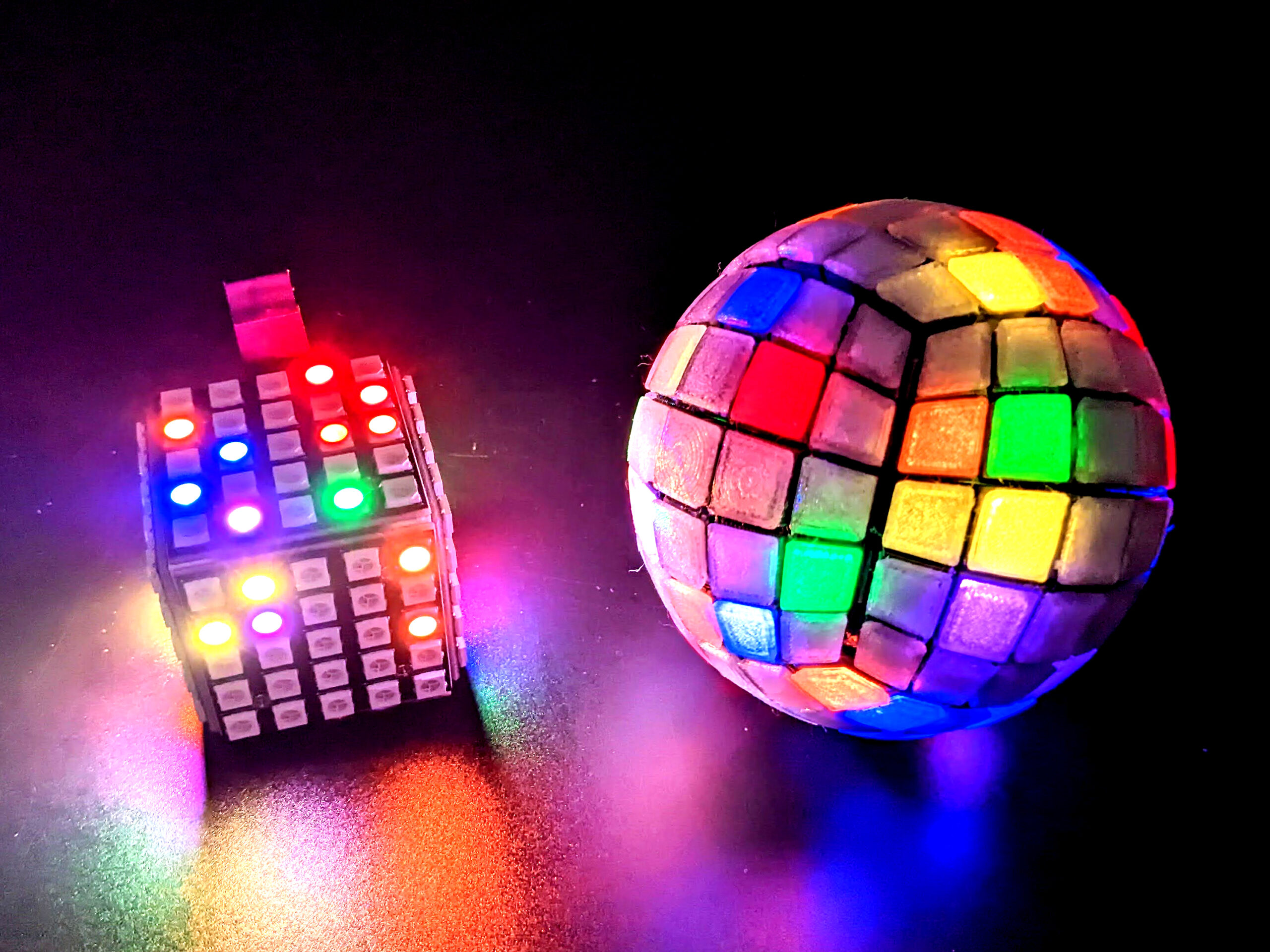
The next design iteration fixed the light bleed problem using opaque shells with one channel per LED to isolate and pipe light to the orb’s surface (Figure A ). Each channel is capped with a translucent curved tile which diffuses the light over a single quad-sphere pixel. Figure B
 shows the magical “bef-ORB and after” transformation of a 5×5 LED cube to its final Cube Orb form.

BUILD YOUR LED CUBE ORB
1. Print the parts
Download the build files for this project. Start by 3D printing the interior connectors and custom battery holder from the file AllConnectors5x5.stl. These small connectors contain thin walls and fine detail and are best printed from PETG for strength and flexibility. Print them in any color PETG with a 0.1mm layer height setting (Figure  D).
D).

Next, print six of the rounded shells from the file Shell.stl. Depending on your printer’s bed size, you may be able to print multiple shell pieces in a single session. Use an opaque, reflective PETG filament like Overture Space Gray with a layer height of 0.2mm and 40% infill. Total print time for all six shell pieces is about 9 hours and can take place while you build the base LED cube.
Finally, print the translucent tiles from the file Tiles.stl, using clear PETG or PLA filament at 0.1mm layer height and 100% infill. If your slicer allows variable layer height, you can speed up the print by using 0.2mm layer height everywhere except the parts above 3mm and between 1.0 and 1.6mm, where the layer height should be 0.1mm or smaller. Watch your printer carefully as the first several layers go down. You may find it helpful to apply a layer of Elmer’s glue stick on the print bed to help them adhere.

Don’t detach the finished tiles from the print bed (Figure E ) until you’re ready to glue them into place on the shell. The tiles may appear identical, but their individual positions and orientation are important! Once they get mixed up, sorting them out becomes a very painful 3D jigsaw puzzle. It’s best to carefully loosen one row of tiles at a time from the build plate and glue it in place before detaching the next row. If you must remove the tiles from the print bed before you’re ready to glue them to the shell, try to maintain their positions by attaching them to a sticky surface such as a wide strip of masking tape.

To secure each row of tiles, apply a thin line of super glue gel along the top edges of the shell’s corresponding row (Figure F ). One at a time, set each tile into its corresponding channel, being careful not to super-glue your fingers. The tile should settle comfortably into its channel but won’t snap into place. If the fit seems awkward, double check the tile’s orientation. Tile edges are wider closer to the center of the shell. Once all tiles are seated, gently press down on them to ensure good contact with the shell, then set it aside to dry for at least 2 hours.
Repeat for the other 5 shells.
2. Build the cube body
For clarity, I’ll refer to each matrix by its position in the final assembly — bottom, right, front, left, back, and top — and each 3D printed connector by the specific name shown in Figure G . The “Matrix Order” referenced in this image is the sequence in which the LED data signal travels between the matrices in the assembled cube.

We’ll first build the cube body, consisting of the right, front, left, and bottom matrices. Lay three 5×5 LED matrices in a row so that the input pads of one sit next to the output pads of another. Heat your soldering iron and tin all pads which sit adjacent to a neighboring matrix, forming rounded solder blobs that cover most of the pad (Figure  H).
H).

Before soldering the matrices together, secure them at right angles using the body brackets, lid brackets (temporarily), and 5mm M2 screws and nuts as shown in Figure  I. All screw heads in the LED cube assembly sit on the LED side of the matrices.

Next, connect the perpendicular solder pads on adjacent LED matrices by melting “bridges” of solder between them. To form each bridge, melt a drop of solder onto the tip of your iron, then place it onto a tinned pad. Once it has merged into the solder on the pad, drag the iron to the adjacent pad, then quickly remove the iron, leaving a narrow solder strip which joins the two pads together. Take care not to melt the PETG connectors.
After the three matrices are connected by solder bridges, unscrew and remove the lid bracket connectors, but leave the body bracket connectors in place (Figure J ).
).

3. Make a custom battery holder
The slim 3D-printed battery holder is needed to fit the 16340 Li-ion battery inside the compact cube interior. The Xiao nRF52840 Sense controller has a built-in circuit that charges the battery while the Sense board is connected to USB power.

Gather the battery holder and two male AAA battery contacts and cut two approximately 5cm pieces of solid core 26 AWG hookup wire in red and black (Figure K ). Strip 5mm of insulation from one end of the wires and push each through the hole in a male battery contact’s stem. Solder the wires to the contacts.
Next, slip the contacts’ wires through the small holes in the bottom of the battery holder, red at the end marked “+” and black at the end marked “–”. Gently slide the contacts down into the narrow slots in the holder’s sides so that the contacts’ bumps point towards the battery holder’s interior (Figure  L). You may need to push them gently with pliers to seat them fully.

Trim the red and black wires about 1cm away from the position where each exits the bottom of the battery holder and strip about 0.5cm of insulation from the end. If you’re using the optional power switch, solder it to the stripped end of the red wire.
Next, cut two red wires and two black wires 4cm long and solder them to the same color wire extending from the battery holder. This lets us split battery power between the Xiao Sense controller and the LED matrices. If you placed a power switch in the circuit, solder the two red wires to the switch instead of directly to the red wire.

Cover the solder joins with heat-shrink tube and heat it until it contracts it over the wires (Figure M ). If you used a slide switch, cover any exposed copper pads on the switch with shrink tube or tape to help prevent short circuits within the cube.
4. Complete the cube body
Next, we’ll connect the bottom LED matrix and Xiao Sense controller to the LED cube assembly. Take one of the 5×5 matrices and tin the Vcc pads, Data pads, and one Ground pad on each side. Solder one of the battery holder’s power leads and one of its ground leads to the Vcc and Ground pads on the data input side of this matrix. Solder the remaining power and ground leads from the battery to the small battery power and ground pads on the back of the Xiao nRF52840 Sense board (Figure N ).
).

Cut and solder a data wire about the same length as the Vcc and Ground wires from the bottom matrix’s data In pad to pin 4 on the Xiao Sense board (Figure  O). Then cut and solder three pieces of 26 AWG solid core wire, each about 4cm long, to the data Out, Vcc, and Ground pads on the output side of the matrix. These will connect the output from the bottom matrix to the input on the right matrix.

We’ll secure the Xiao Sense mechanically inside the cube with 3D-printed connectors. Take the two Xiao brackets and slide them over the Xiao Sense board from both sides as shown in Figure P . The skinny, long “arm” extending from each of these brackets fits just below the Xiao’s USB-C connector. Carefully slide the 3D-printed connectors and Xiao into the cube, with the Xiao parallel to the front matrix. Align the brackets’ holes with the holes along the cube body’s top edges. Using four 5mm M2 screws and nuts, fasten the Xiao brackets to the cube body, again with the screw heads on the cube’s exterior.

Next, attach the bottom matrix to the LED cube body assembly by fastening it to the 3D-printed body brackets using two 5mm M2 screws and nuts. During this process, carefully guide the wires extending from the bottom matrix so they sit inside the cube. Once the bottom matrix is fastened to the body brackets, bend and trim the wires from its output pads so that they terminate at the input pads on the right matrix. Strip the ends and solder the wires directly to the right matrix input pads (Figure  Q).
Q).

Before powering the circuit, use a continuity meter to test for short circuits inside the matrix body. Inspect the cube carefully to find any loose nuts or screws which may have fallen inside, as they can cause dangerous shorts if they contact the solder bridges inside the cube.
5. Test the cube with CircuitPython code
If no shorts exist, connect a USB-C cable from your computer to the Xiao board to power it on. Install CircuitPython, searching for the Xiao nRF52840 Sense board, and downloading its UF2 file. Put the Xiao Sense in bootloader mode by double clicking the very, very tiny reset button just to the left of the USB-C connector. You may need to use a pencil tip or screwdriver head to press the button (Figure  R).
R).

When the Xiao Sense enters bootloader mode, it will show up on your computer as a drive named XIAO-SENSE (Figure  S). Drag and drop the UF2 file you downloaded onto this drive. After the file is fully copied over, the Xiao Sense will reboot and appear as a drive labeled CIRCUITPY.

To test the wiring thus far, we’ll insert a battery into the holder and run a simple CircuitPython NeoPixel animation program. Download and unzip the CircuitPython Library Bundle , Copy the neopixel.mpy library into the lib folder on the CIRCUITPY drive. Delete the default code.py program from the CIRCUITPY drive, then copy the program examples/neopixel_simpletest.py from the library bundle folder to the CIRCUITPY drive. Rename it code.py.
Using the Mu code editor in CircuitPython mode, or your preferred CircuitPython editor, open your new code.py file and make two changes to reflect the cube’s wiring:
• Change pixel_pin = board.NEOPIXEL to pixel_pin = board.D4
• Change num_pixels = 10 to num_pixels = 100
Once you save the edited code.py file, the program will start running, and the cube body’s LEDs should display alternating red, green, blue, and rainbow colors. If that doesn’t happen, check that the battery is well seated in the holder. 
After the circuit is tested and working, unplug the Xiao from your computer and remove the battery from its holder to safely continue cube assembly.
TIP: Cylindrical 16340 batteries can vary in size, and some are just slightly too short to make a good connection with the battery holder contacts. If this happens, you can extend the battery’s power terminals slightly with small pieces of copper tape (Figure T) or melt small blobs of solder on the holder’s contacts to bring them in slightly so they’ll touch the battery terminals. Do not apply solder to the battery’s terminals, only to the metal contacts in the 3D-printed battery holder.

6. Connect the JST cable
The next step is soldering the tiny JST connector cable to the main cube body. Take the small male 3-pin JST cable, trim it to about 7cm, and solder the red, black, and yellow wires to the Vcc, Ground, and data Out pins, respectively, on the left matrix. To prevent the cable interfering with the cube lid closing, the wires should run from these pads back into the body of the cube (Figure  U).
U).

Now, using small pieces of CosBond adhesive or gaffer tape, tape the wires down on inside of the left matrix near the solder pads to provide strain relief when the lid is opened (Figure  V).
V).

7. Put a lid on it
Now we’ll construct the cube lid. Take the two remaining 5×5 WS2812B matrices and tin the input pads on one and the output pads on the other. Use the 3D-printed lid brackets and four 5mm M2 screws and nuts to attach the matrices at right angles. Heat your soldering iron and bridge adjacent solder pads together to complete the lid’s circuit (Figure  W).
W).

Take the small female 3-pin JST cable and trim it to about 3cm long. Strip its ends and solder the red, black, and yellow wires to the available input Vcc, ground, and data pads on the back matrix, orienting the cable so that the wires lie flat along the back matrix. Apply small pieces of CosBond adhesive or tape to adhere the cable to the matrix and provide strain relief (Figure  X).
X).

Now that the electrical circuits are completed, we’ll install the magnetic connectors that hold the lid to the cube body. Use two 6mm (5mm will be too short) M2 flathead screws and nuts to attach two of the countersunk 1/8"×¼" magnets into the cylindrical recesses in the 3D-printed body latch connectors. If you’re not using countersunk magnets, then glue two 1/8"×¼" disc magnets in their place, seating the magnets as far back into their recesses as they will go. After the magnets are secured, insert two M2 nuts into the captive nut slots in each body latch, and, using two 5mm M2 screws, fasten each body latch to the bottom matrix and the adjacent right or left matrix (Figure Y ). Once the cube’s lid is closed, it can be hard to locate the opening, so it is helpful to make a tab, several centimeters long, from a piece of tape folded over itself and attach it to the unsoldered edge of the cube lid, as seen in Figure
  Z.
Z.


Double check the electrical wiring by first testing for shorts between Vcc and Ground with a continuity tester. If no shorts exist, connect the mini JST cable between cube lid and body, insert the 16340 battery into its holder, and run the same simple LED animation as before on the Xiao. Change the num_pixels variable’s value from 100 to 150 to illuminate the LEDs in the cube lid as well as the body. If the patterns display correctly on all six matrices, your cube is complete — and ready to become more well-rounded.
8. Shell game: Take the edge off
In this last assembly step, we’ll attach the 3D-printed shell pieces to create Cube Orb’s final form.
Cut and place small strips of 2mm wide double-sided tape across the rows on the shell’s underside, leaving the red plastic cover layer on each tape strip until all rows are placed. Then peel the red plastic from each row of tape, and lay columns of tape across each of the rows (Figure  Aa).
Aa).

Finally, peel the red plastic cover from each tape column and gently but firmly stick the shell to one matrix in the cube (Figure Bb ). The tape provides a secure hold which stands up to reasonable handling but is still detachable, allowing access to the screws sitting underneath the shell pieces.

Repeat with the other five shells. Once all six are in place, take a moment to ponder Cube Orb’s spherical perfection!
9. Program the Orb
Most of Adafruit’s clever CircuitPython LED Animation library patterns look great running on Cube Orb. You can find out more in their excellent Learn Guide. The LED Animation library also provides a useful basis for our code, because it manages animation timing, RGB pixel color generation, and pattern “playlists” which can be advanced automatically or by external triggers such as Bluetooth input or gesture detection.
Our animation, named “Tilt,” uses input from the Xiao Sense board’s accelerometer to determine its orientation. It displays a colorful “bullseye” that always fills Cube Orb’s upper hemisphere, regardless of its orientation (Figure Cc ).
).

To get Tilt running on Cube Orb, download the project code from and then copy the files code.py, coordinates.py, imu.py, orb.py, and tilt.py to the top level of your CIRCUITPY drive. You will also need to copy the Adafruit CircuitPython libraries adafruit_led_animation, adafruit_lsm6ds, and adafruit_register into the lib folder on your CIRCUITPY drive. With all files in place, the Tilt animation should start to run, and the illuminated pixels will remain on top, no matter now you rotate the orb.
Comments in the code files explain the functions in detail, but here’s a general overview:
• The spatial coordinates of Cube Orb’s 150 pixels are computed using the Matrix and Orb classes, defined in orb.py. The Matrix class stores the coordinates of the first pixel in each matrix, the direction of the matrix’s rows and columns, and the row layout (parallel or zig-zag). The Orb class takes a list of Matrix objects, one for each of its physical LED matrices, and uses the properties of each matrix plus a little bit of math to project the matrix pixels to the orb’s surface and store their Cartesian coordinates.
• In the main program file, code.py, the Matrix object properties are specified in the orb5x5() function which returns an Orb object. If your LED matrices have a different layout than the ones used in this project, you will need to change the matrix definitions here to reflect your orb’s physical layout.
• An IMU class, defined in imu.py, obtains the data from the Xiao Sense’s accelerometer. The Tilt animation, defined in tilt.py, takes an IMU object as a parameter, as well as the LEDs’ spatial coordinates. The Tilt() class gets all the functionality of the Animation class through Python inheritance and overrides the Animation class’ draw() function, which is called once in each animation frame to set LED colors. Each time it is called, the draw() function obtains accelerometer readings from the IMU, computes pitch (rotation about the X-axis) and roll (rotation about the Y-axis) angles, then uses them to transform the pixel coordinates to match the orb’s real-world orientation. The draw() function fills all pixels in the upper hemisphere with colors determined by each pixel’s vertical (Z-axis) coordinate.
The Tilt animation provides a template to code your own CircuitPython LED animations which respond to Cube Orb’s orientation. If you’re not sure where to start, copy the Tilt code and make small changes to its draw() function, then save your changes to see the animation patterns change in real time.
FURTHER ORB-JECTIVES
If you’d like to go further with Cube Orb, here are some ideas to consider.
• Create an animation playlist using Adafruit’s Animation Sequence class from the LED Animations library
• Include sound reactivity using readings from the Xiao Sense’s built-in microphone
• Explore Bluetooth control to switch between patterns, using Adafruit’s Bluefruit App to control the Xiao Sense (This is a good reference)
• The Sense board has a gyroscope as well as an accelerometer. If you’re looking to get a bit more mathematical, do a bit of research on using a complementary or Kalman filter to combine the gyroscope and accelerometer data and improve the accuracy of the orientation calculations, then implement it in the code.
There is a definite magic in watching LED animations play across the surface of a sphere, but no wizardry is needed to assemble your own Cube Orb, just a bit of care and persistence. I’m willing to bet that, if you give it a try, you’ll find this project as abs-ORB-ing as I have. 
ORB-SESSIVE BEHAVIOR
My happiness with Cube Orb turned quickly into an all-consuming ORB-session. I created three different orb designs based on the most commonly available WS2812B LED matrix sizes. Figure C shows Orbs built from 4×4, 5×5, and 8×8 matrices. The smaller (ad-ORB-able!) 4×4 and 5×5 Cube Orbs are each controlled by Seeed Xiao nRF52840 Sense microcontroller, which fits an IMU, microphone, and Bluetooth into a tiny, 21mm×17.5mm footprint.
The larger 8×8 Cube Orb runs a long series of intricate, customizable patterns on Ben Hencke’s powerful Pixelblaze controller and Sensor Board, which I used previously in my Pixelblaze Pillows project ; see Make: Volume 83 for this article and more on the Pixelblaze controller).
All three orb designs contain an LED cube consisting of a body of four connected matrices and a detachable two-matrix lid secured by magnets. However, the different sized matrices have varying solder pad and mounting hole placements, so each requires a unique internal structure and assembly process to create the LED cube interior. The 4×4 and 8×8 cube designs have extremely tight tolerances requiring a great deal of patience and excellent soldering and construction skills. Additionally, the 8×8 build requires about 90 hours of 3D printing time vs. about 27 hours for the 5×5 version. The 5×5 cube is a much more forgiving, though still intermediate-level, build.
This article describes the steps to build the 5×5 LED matrix version of Cube Orb. Information on the significantly more challenging 4×4 and 8×8 builds is online here.


