

This guide will cover the basic concept of the Ping))) sensor by making a fun project.
Projects from Make: Magazine
Parallax Ping))) Theremin
This guide will show you how to make a simple distance theremin/ruler with the Arduino.
Wire LCD backlight/logic circuits
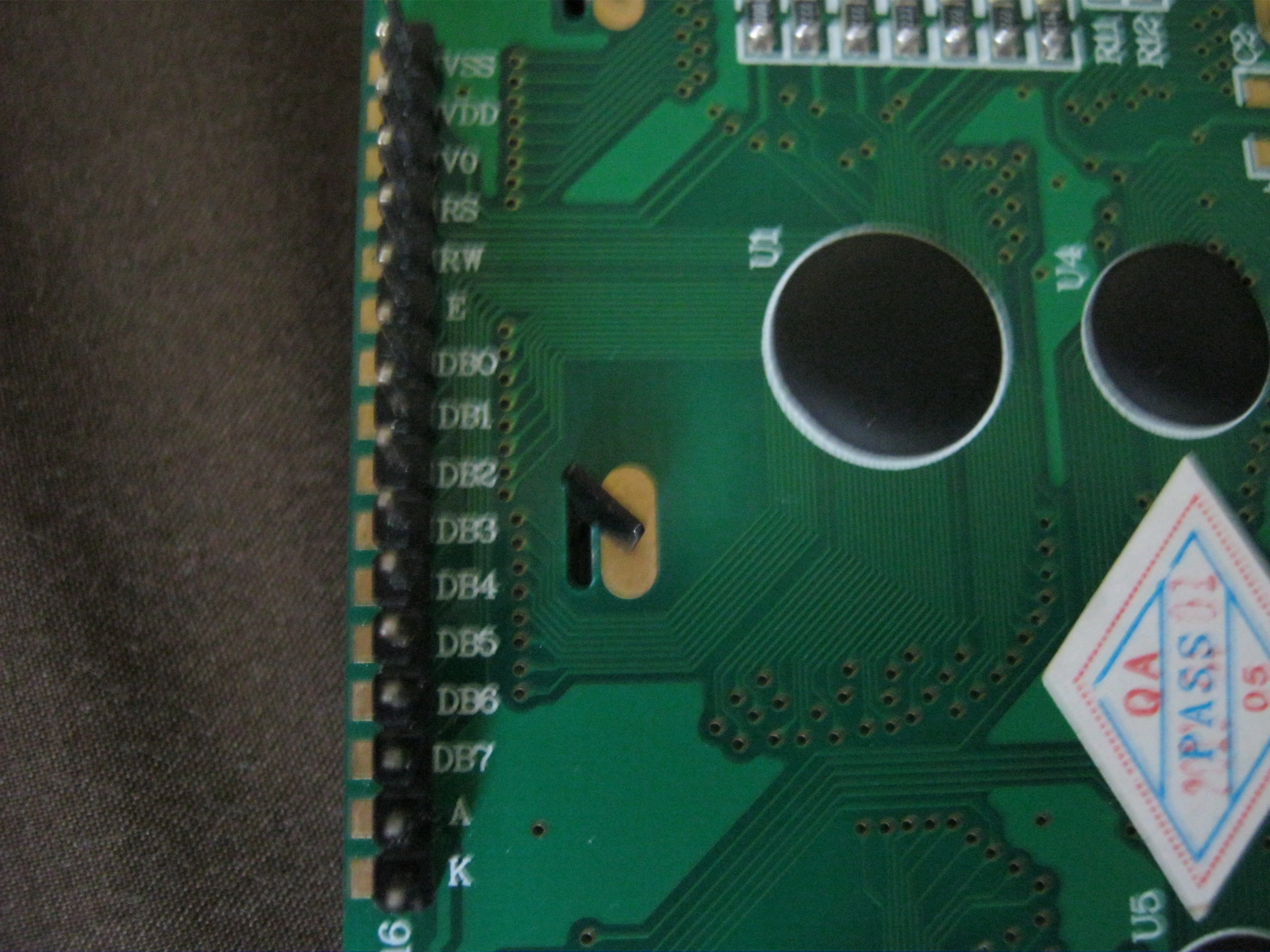
Wire backlight according to pins on LCD. Same for logic circuits. Pot wiper goes to Vo (contrast), one outer pin of the pot goes to ground, the other to 5v.
Make sure polarities are correct.
Use pot to control contrast to your needs.
Wire the digital pins

* LCD RS pin to digital pin 12 * LCD Enable pin to digital pin 11 * LCD D4 pin to digital pin 5 * LCD D5 pin to digital pin 4 * LCD D6 pin to digital pin 3 * LCD D7 pin to digital pin 2 * LCD R/W to ground
I used a 1K resistor instead of a 10K pot.
Use the 10K pot to control the contrast.
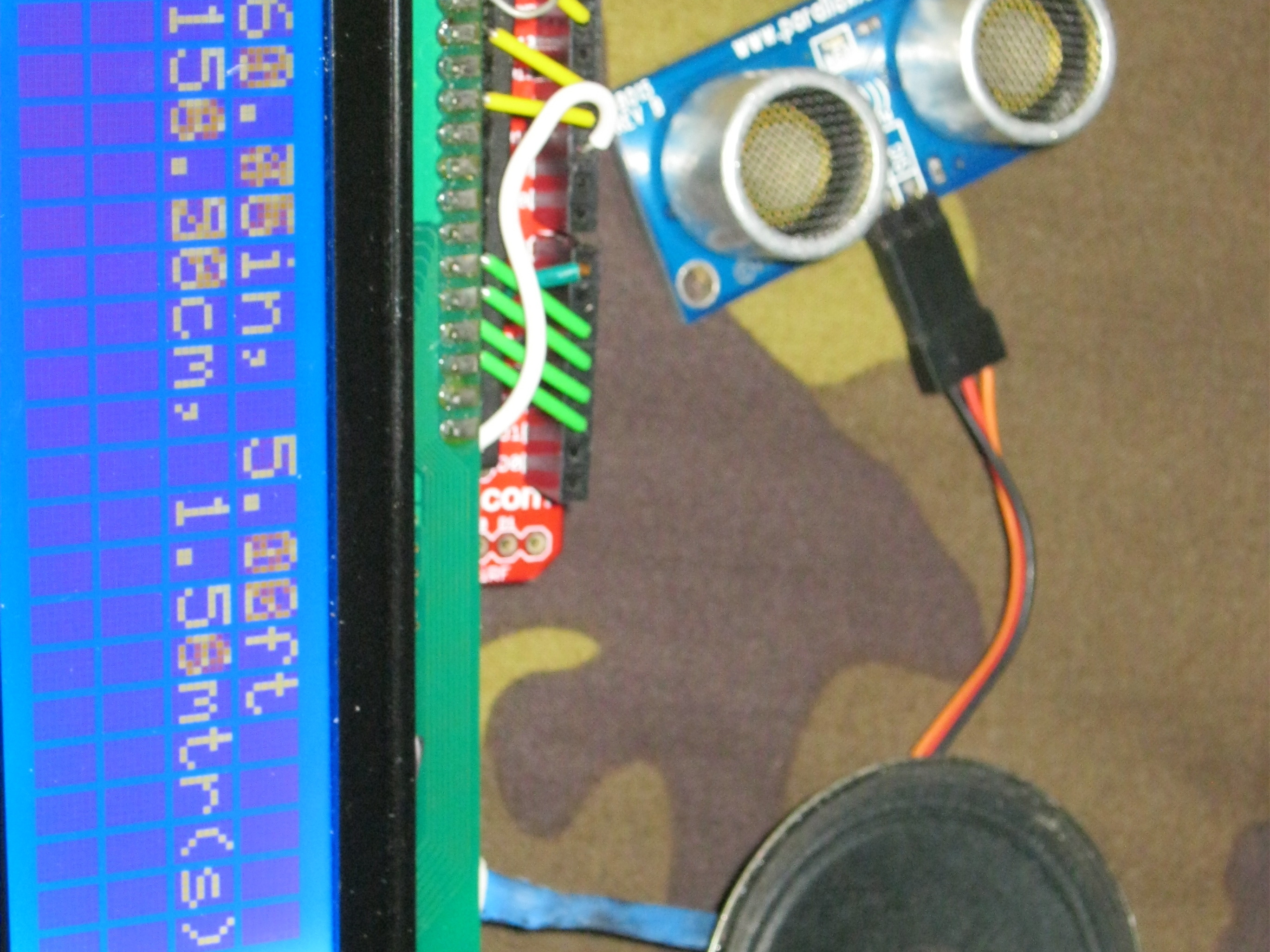
Wire Ping))) and audio

Sound is on pin 10 and ping is on pin 7. 1kΩ resistor on headphone ground.
Upload code

Code can be found here.
Copy and paste code to Arduino IDE and click “Upload”.


