


My brother-in-law Chris wants to build a wood-fired pizza oven in his backyard. Chris is an aspiring pizza chef at night, but a process engineer by day. Although his pizza oven will be built from age old sand and clay, veins of chromium and aluminum will be running through the walls. These veins are thermocouples, a precision temperature measurement sensor. Four of these thermocouples meet back at the PiMometer, a custom-made circuit board and Raspberry Pi combo. Temperatures from throughout the oven will be displayed on a continuously updating webpage viewable from any smartphone or PC.
Thermocouple Basics
Thermocouples are digital thermometers that are both accurate and suitable for the searing hot fires of a wood oven. They are made of two types of very specific metals, that when heated or cooled generate a voltage across their terminals. The PiMometer uses Type K thermocouples, made of alumel (alloy of nickel, aluminum, and other metals) and chromel (alloy of nickel and chromium). Type Ks are good up to 2,000°F, hot enough to melt pure copper and much hotter than the pizza oven will get.
The voltage generated by the thermocouple depends on the change in temperature. This voltage is very small, only a few thousandths of a volt, so it must be amplified before it can be measured. While there are analog thermocouple amplifiers out there, the PiMometer uses a digital chip, the MAX31855. This chip requires no external components and can provide the temperature to the nearest half of a degree. The temperature is provided back to the Raspberry Pi using a protocol called Serial Peripheral Interface (SPI).
SPI Overview
SPI (along with I2C) is one of several serial communication protocols supported by the Raspberry Pi. It is incredibly easy to use, making a great protocol to start learning about new hardware interfaces. In general, a single SPI bus can be used to link multiple devices, as we connect one Raspberry Pi to four MAX31855s. SPI uses either three or four connections from the Raspberry Pi to the MAX31855. The connections are as follows:
- Clock (CLK) — This signal pulses at regular intervals, keeping the RPi and MAX31855 in lock step. When this line changes, both sender and listener agree to move on to the next stage of the communication. A single CLK signal is shared between all parties on a bus.
- Chip Select/Enable (CS/CE) — This line chooses which chip (of the four MAX31855s) is active at a given time. Each party on the bus has a separate CS line.
- Master In, Slave Out (MISO) — This line sends data from the slave (MAX31855) on the bus currently chosen by the CS setting back to the master. It is over this line that the actual temperature data is communicated. A single MISO signal is shared between all parties on a bus.
- Master Out, Slave In (MOSI) — Although not used in this project, this line sends data from the master on the bus to the slave currently chosen by the the CS setting. A single MOSI signal is shared between all parties on a bus.
The temperature data is pulled from the thermocouple chips using a Python script. This script is called from and returns its data back to a node.js server.
node.js
node.js is the web server framework used by the PiMometer. It is responsible for hosting the webpage that displays temperature data to the user. When a user accesses the PiMometer’s web page, node.js will serve up the page (including fancy bar charts) and then begin pushing updates to the page once per second. The updates come from a Python script that queries all MAX31855s over SPI.
Construction of the PiMometer
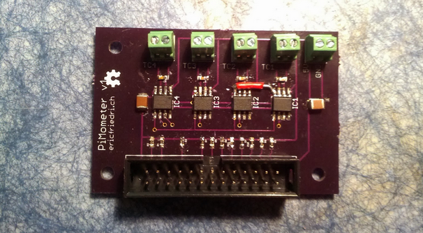
The circuit board for the PiMometer was designed in Eagle CAD and based on Adafruit’s MAX31855 breakout board. A single SPI bus was used to link all chips back to the Raspberry Pi. The Raspberry Pi provides a hardware SPI device that was unused here because it only supports two SPI devices. The PiMometer needed four thermocouples (which have a low data rate), so basic GPIO ports were used. The boards were fabbed by OSH Park. They were soldered by hand, my first successful attempt at surface mount (SMT) soldering. Only one piece of rework was needed on the PCB: a trace which was not routed all the way to the pad of a chip. You can see this red-wire fix in some of the photos.
Everything you need to build your own PiMometer (Eagle files, code, etc…) is available on my Github page.


