YouTube player

Build a digital guardian for your favorite plants! Using an Arduino and a few inexpensive sensors, you can keep your plants extremely happy with the proper amount of moisture, warmth, and light.

The simplest version of Potted Plant Protector senses the brightness of the light, wetness of the soil, and warmth of the air that your plant is exposed to. It outputs these readings over USB, displaying on your computer screen. You’ll start by building this simple monitor, and then move on to intermediate and advanced builds that incorporate LED and LCD displays, learning about Arduino and electronics as we go.

All electronic parts for all three versions are available at Radio Shack in the Make: Ultimate Microcontroller Pack. They can also be purchased separately.

Project Steps

Basic build: Light, heat, and moisture sensing.

For the basic build you’ll need the Arduino Uno microcontroller, solderless breadboard, three 10kΩ resistors, jumper wires, a thermistor (temperature sensor), a photoresistor (light sensor), and the steel bolts and nuts.

You’ll also need to make 2 spacers for your soil probes (the bolts). In a scrap of plastic, drill 2 holes 1/2″ to fit your bolts. Make a second spacer and thread your bolts through both spacers, to keep them separated at a distance that won’t vary.

I calibrated a fancier soil sensor by laser-cutting some 1/16” acrylic to serve as a separator between small pieces of 1/16”-diameter stainless steel rod, commonly used for TIG welding. Cut files for the acrylic are available here .

Build the 3-sensor circuit.

The 3 different sensors you’ll use all operate the same way, by providing electrical resistance that varies depending on the amount of soil moisture, or heat, or light, that’s detected. Generally, you can use a simple circuit like the one shown in the first schematic to read a variable resistance on an Arduino.

Here we’ll use this setup for our 3 sensors — soil moisture, temperature, and light — and put them all together to create the circuit shown in the second schematic.

Following the schematic, build the circuit on the breadboard as shown in the third photo. The thermistor and photoresistor are on the breadboard; the soil probe is just 2 long wires, each wrapped around a bolt and secured with a nut. The soil probe is connected to the Arduino’s analog pin A0, the thermistor to pin A1, and the photoresistor to pin A2.

Program the Arduino.

Generally, we read a variable-resistance sensor attached to an analog input on the Arduino with the following code:

sensorValue = analogRead(inputPin);

where sensorValue is the reading from the sensor and inputPin is the number of the analog pin to which the sensor is attached

To read the 3 sensors, we simply repeat this code for all 3 sensors, add variable declarations, and set up our serial port. Here’s the resulting code — download it from this link, open it in the Arduino IDE, and upload it to your Arduino.

Place and calibrate sensors.

Poke the soil sensor into the soil next to your plant, mount the photosensor where it will receive the same amount of light as your plant’s leaves, and mount the thermistor next to the photosensor. Power up the Arduino and watch the Serial Monitor on your computer to see the sensor values, updated every second.

For the best potted plant protection, you’ll want to calibrate your sensors to the range of conditions desired by your particular plant. Your local Master Gardener is a good resource for asking questions like “Is this how wet the soil should be when it’s watered enough? Is this how dry the soil should be when it’s time to water?” Then take readings with your Potted Plant Protector to quantify those values.

You can also borrow a fancier sensor and calibrate your inexpensive ones to it. Here are readings I took with an industrial soil moisture sensor compared to the Arduino values from my DIY welding-rod soil probe:

  • In open air: both sensors read 0
  • Very dry soil: 2% Vegetronix, 5 DIY
  • Slightly moist: 7%, 150
  • Slightly moister: 8%, 250
  • Wet soil: 28%, 370
  • Very wet soil: 51%, 385
  • Probe immersed in water: 85%, 480

So if I want to water my soil to about 28% moisture, I should watch for a sensor reading of about 385 as my cutoff point.

Intermediate build: Add an RGB LED indicator.

Now, you’ll add an LED to indicate how happy your plants are. I’m using blue to indicate water neediness, green for sunlight, and red for temperature, all displayed by a single RGB LED. (Of course, you have plenty of other options!) Grab the RGB LED and three 330Ω resistors.

Generally, you can connect an LED to an Arduino with the circuit shown in the first diagram here. On the schematic symbol for an LED, the triangle points to the anode (negative side). On an actual LED, the longer lead is the one you’ll connect to ground. (I’ve broken some expensive LEDs by hooking them up backward!)

The resistor regulates current to the LED: too much current, and our LED will burn out after a couple of seconds rather than lasting the 10,000-odd hours that it should.

Connect the LED into your circuit.

With an RGB LED, it’s common for the red, green, and blue elements to have a common cathode or common anode, resulting in 4 pins (check your datasheet to determine if a specific RGB LED is shared anode or shared cathode). The RGB LED in the Make: Ultimate Microcontroller Pack is common anode, so we’ll connect it as shown in the schematic here.

Following the schematic, connect the LED to +5V power and to the Arduino’s digital input/output (I/O) pins D9, D10, and D11.

Reprogram the Arduino.

The big new concept here is calling functions: instead of typing the same code over and over again, we can put it in a function and just call that function. For example, here’s how we turn all 3 colors off for the LED:

digitalWrite(redPin, HIGH);

digitalWrite(greenPin, HIGH);

digitalWrite(bluePin, HIGH);

Instead of typing this every time we want our LED to go off, we can put it in a function:

void off()

{

digitalWrite(redPin, HIGH);

digitalWrite(greenPin, HIGH);

digitalWrite(bluePin, HIGH);

}

Now, we can run this code whenever we want by calling the function off();. This is the simplest use of functions. As you learn more about programming, you’ll do all kinds of cooler, more complex things with them.

Here’s the resulting code — download it from this link, open it in the Arduino IDE, and upload it to your Arduino.

This will cycle our LED through its different colors over the course of 5 seconds, depending on our plant’s conditions:

  • The LED will flash blue for 1 second if the soil is moist
  • The LED will flash red if our plants are warm
  • The LED will flash green if our plants are getting sun

Advanced: Display readings on an LCD screen.

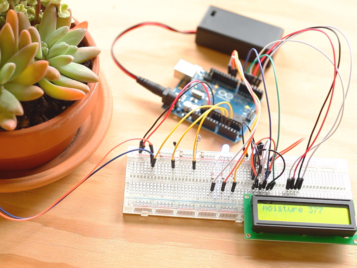
Now, you’ll add an LCD text display to cycle through the 3 sensor readings, displaying each reading for 4 seconds (while still lighting the LED with the appropriate color when conditions match those that we set in the intermediate example). Grab the 16-pin LCD display and the 10kΩ potentiometer from the Make: Ultimate Microcontroller Pack.

You’ll need to do some soldering to wire up the LCD screen. If you’ve never soldered before, don’t worry! It’s easy if you use good tools and proper technique. Our celebrity soldering tutorial is a great place to start learning.

Connect the LCD display and test it.

You’ll connect the display slightly differently than you would if you only had the LCD connected. Do not worry, we will just give you what you need to know for the project! For the curious, check out

http://arduino.cc/en/Tutorial/LiquidCrystalDisplay

Following the schematic, connect the LCD into your circuit:

  • LCD pin #1 to Ground on your breadboard
  • LCD pin #2 to 5V and also the potentiometer outer pin –does not matter which outer pin, just pick one.
  • LCD pin #3 to the potentiometer wiper –that is the middle pin.
  • LCD pin #4 to the Arduino digital pin #7 –this is different from the stock LCD Library.
  • LCD pin #5 to GND and also the potentiometer´s other outer pin.
  • LCD pin #6 to the Arduino digital pin #6 –this is different from the stock LCD Library.
  • LCD pins #7 – #10 do not connect to anything.
  • LCD pin #11 to the Arduino digital pin #5
  • LCD pin #12 to the Arduino digital pin #4
  • LCD pin #13 to the Arduino digital pin #3
  • LCD pin #14 to the Arduino digital pin #2
  • LCD pins #14 and #15 do not connect to anything.

The Arduino tutorial referenced above provides everything you need to drive the LCD. To test your LCD, here’s their sample code, adapted for our pins. Download it from this link and upload it to the Arduino, then be sure to turn the potentiometer until you can see “hello world” displayed on the screen. If your LCD is connected correctly, this should blink on and off every second.

Reprogram the Arduino.

Now, here’s the complete Potted Plant Protector code with the LCD added. Once you’re satisfied your LCD is working, download the code from this link and upload it to the Arduino.

Growing Further

That’s it! Now your plants can tell you exactly what they need, exactly when they need it. Here are some advanced options for really making your Potted Plant Protector bloom:

Controls: Add a relay shield (RadioShack #277-067) to control water pumps, heaters, or lights for your plants. You’ll want to explore the Arduino time library (http://playground.arduino.cc/Code/time) for tasks like “turn on lights so that sunlight + supplemental lights add up to 16 hours per day.”

Power management: Make your Arduino go to sleep and only wake up for readings every few minutes to drastically extend battery life. Simple ( http://hwstartup.wordpress.com/2013/03/11/how-to-run-an-arduino-on-a-9v-battery-for-weeks-or-months/ ) and advanced ( ) guides are available; this will also drastically extend the life of your soil probes before they start to corrode.

Solar power: Add a solar panel and battery to power your plant protector off-grid (http://voltaicsystems.com/blog/solar-powered-automated-garden/).

Connectivity: Share your data with others and access it remotely with an Ethernet shield (RadioShack #276-241), Wi-Fi shield (http://growerbot.com), or even a cellular shield.

Better sensors: Explore the many sensor options, including pH, light spectrum, and humidity, to graduate your Potted Plant Protector to the next level of science!