The Oxocard Connect is a versatile microcontroller board with plug-in cartridges for making all kinds of electronic projects. It has been designed to be programmed in NanoPy, a beginner-friendly language similar to Python, but this is not the only option. You can also program the Oxocard Connect using CircuitPython, a popular Python implementation for microcontrollers. In this article we’ll cover how to install of CircuitPython, the basics of programming with it, and some simple experiments to get you started.

Project Steps

Installing CircuitPython

The simplest way to install CircuitPython on the Oxocard Connect is to use the web installer provided by CircuitPython. It uses WebUSB and requires a compatible browser; it works best with Google Chrome or Microsoft Edge. (Firefox and Safari do not support WebUSB.)

1. Connect the Oxocard Connect to your computer using a USB cable.

2. Open your browser and go to circuitpython.org/board/oxocard_connect.

3. Choose the language version you want to install (e.g., English).

4. Click on Open Installer to launch the CircuitPython web installer.

5. From here, you can either make a Full Install, or install the Binary Only, or Update the Wi-Fi Credentials. The full install is tempting because it includes the Wi-Fi configuration, but, at the time of writing, this feature was not working properly. So for now, it is safer to choose the Binary Only option.

6. When you see the welcome screen of the installer, click on Next.

7. On the next screen, click on the Connect button to connect to the Oxocard Connect.

8. Your browser shows you a list of USB devices. Select the Oxocard Connect from the list and click on Connect.

9. After a few seconds, the installer warns you that the Oxocard will be erased. Click on Continue to proceed.

10. The installer erases the flash memory and installs CircuitPython. This may take a couple of minutes.

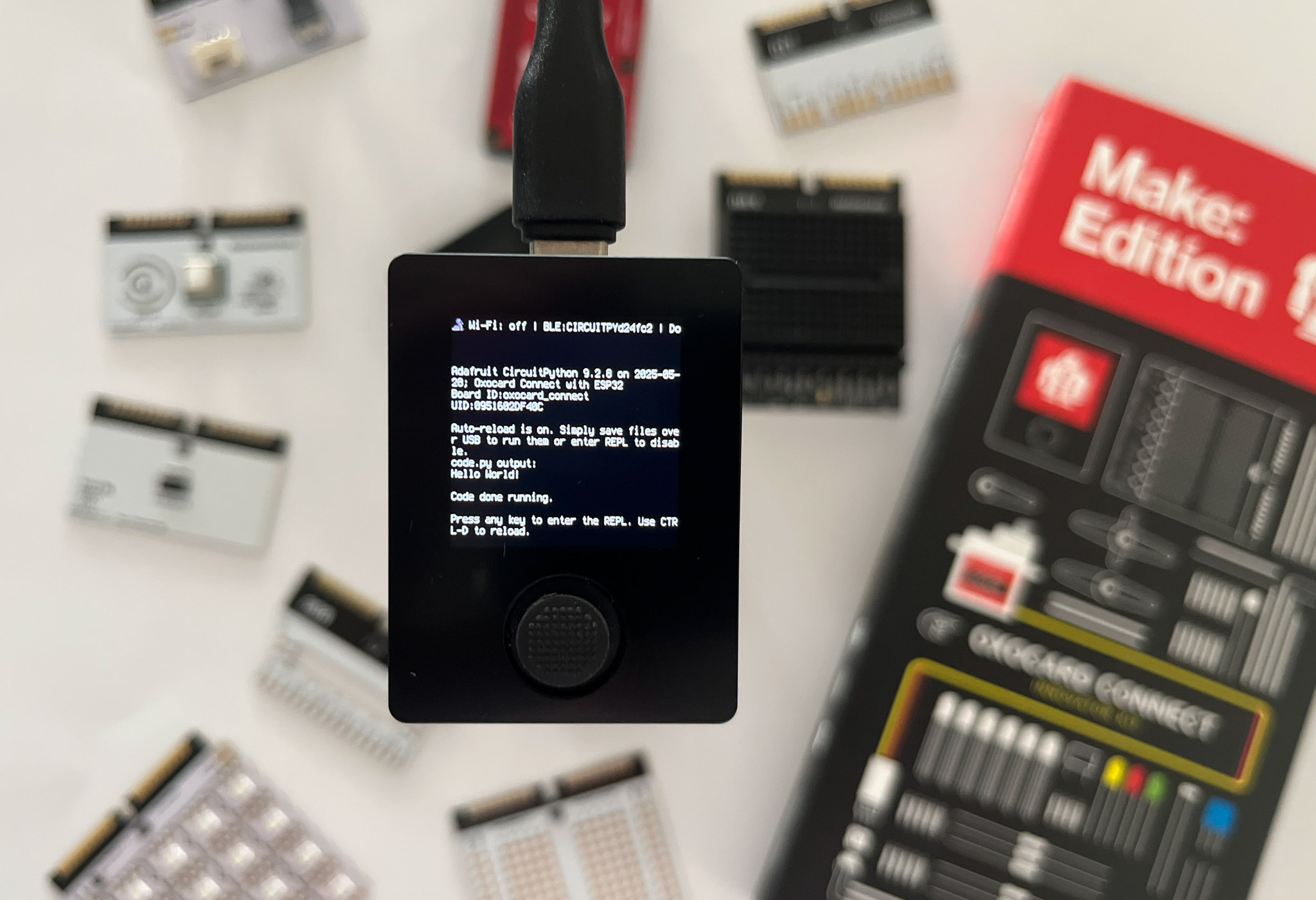
11. If everything goes well, your Oxocard will display some text and you will see a message on your browser saying that the installation was successful. Click on Close to finish the installation.

Getting Started with CircuitPython

CircuitPython is a beginner-friendly version of Python designed for microcontrollers. It is available for many microcontroller boards, including the Oxocard Connect. It provides a simple way to write Python code that interacts with the hardware.

Some boards (for example, boards based on the ESP32-S3 or on Raspberry Pi Pico) act as a USB mass storage device when connected to a computer, so you can simply drag and drop files to the board, like you would with a USB flash drive.

The Oxocard Connect uses a tiny ESP32-PICO chip that does not support this feature, so you’ll need to use a serial connection to upload your code. The easiest way to do this is to use Thonny, a popular Python IDE that supports CircuitPython.

Blinking an LED

When you learn a new programming language, the first program you usually write is called “Hello World.” In the world of microcontrollers, this program is often called “Blinky.” It simply turns an LED on and off at regular intervals.

Before coding this program, let us assemble the hardware for it. Note that there are two ways of connecting an LED to a microcontroller: the microcontroller can either source or sink the current flowing through the LED. In the first case, the microcontroller pin is connected to the anode of the LED and the cathode is connected to ground. In the second case, the cathode is connected to the microcontroller pin and the anode is connected to a positive voltage (usually 3.3V with modern microcontrollers).

Microcontroller sinking current from an LED

The sinking option is often preferred because it usually allows the microcontroller to drive the LED with a higher current. The only drawback is that the microcontroller must set the pin to low to turn the LED on, and set it to high to turn it off. This can be a bit counterintuitive, but it’s not a big deal once you get used to it.

Connect the LED to the Oxocard Connect as shown. The longer leg of the LED (anode) is connected to VDD using a red wire and the shorter leg (cathode) is connected to IO01 through a 220Ω resistor.

Breadboard with the LED and resistor

Download and install the Thonny IDE from thonny.org. Then connect your Oxocard Connect to your computer using a USB cable, and open the Thonny IDE.

The Thonny IDE should automatically detect the Oxocard Connect and connect to it. If not, you can select the Oxocard Connect from the bottom right corner of the Thonny IDE window.

You can now open the code.py file on the Oxocard Connect. This file is the main script that will be executed when the Oxocard Connect starts. You can edit this file directly in the Thonny IDE.

Thonny IDE

Replace the content of the code.py file with the following code:

1 # https://github.com/supcik/Oxocard-Connect-CP-Make-Src/blob/main/src/blinky.py
2 # Blinky with Oxocard Connect and CircuitPython
3
4 import time
5
6 import board
7 import digitalio
8
9 HALF_PERIOD_S = 0.2 # Half period in seconds
10 LED_PIN = board.IO01
11
12
13 def main():
14     led = digitalio.DigitalInOut(LED_PIN)
15     led.switch_to_output(True)
16     while True:
17         led.value = not led.value # Toggle the LED
18         time.sleep(HALF_PERIOD_S)
19
20
21 main() # Run the main function

The code above turns the LED on and off every 200 milliseconds. It uses the digitalio module to control the GPIO pins of the Oxocard Connect.

TIP: You don’t need to type the code manually; you can copy and paste it from above or the source code repository instead. You’ll find it on GitHub.

Below is the Blinky program in the Thonny IDE. To run this program, click on the green arrow in the Thonny IDE. Now you should see the LED blinking on the Oxocard Connect.

Blinky program in Thonny IDE

NOTE: The external LED that you connected on the breadboard is sinking current, but the small green LED on the PCB below the breadboard is sourcing current. This means that both LEDs blink at the same time, but they are in opposite states in the program: when the external LED is on, the small green LED is off, and vice versa.

Adding a Button to Control It

The next experiment is to add a button to the system. For this, we use the joystick button on the Oxocard Connect.

Our goal is to toggle the LED on and off when the button is pressed. The button sends a digital signal to the GPIO pin. On the Oxocard, the signal is zero (or False) when the button is not pressed, and one (or True) when the button is pressed.

The button has only two positions, but as shown below, we define four states:

  • Up: the button is not pressed.
  • Pressed: the button has just been pressed.
  • Down: the button is pressed.
  • Released: the button has just been released.
Button states

We are interested in the Pressed state, which is when the button was Up and is just now going Down. This is the moment when we want to toggle the LED.

We could easily code this behavior ourselves, but CircuitPython provides a convenient way to handle buttons using the Adafruit Debouncer Library.

The easiest way to install this library to your Oxocard connect is to download the library bundle from the CircuitPython website and use the Thonny IDE to copy the library files to the Oxocard Connect.

1. Go to circuitpython.org/libraries and download the latest CircuitPython library bundle for your version of CircuitPython.

2. Extract (unzip) the downloaded ZIP file.

3. Open the Thonny IDE and connect to your Oxocard Connect.

4. In the Thonny IDE, make sure the Files view (the folder icon on the left sidebar) is open.

5. At the top of the Files view, in the “This computer” window, navigate to the folder where you extracted the library bundle, open the /lib folder, and search for the adafruit_debouncer.mpy file.

6. In the bottom part of the Files view (“CircuitPython device” window), open the /lib folder.

7. Left-click on the adafruit_debouncer.mpy file and choose Upload to /lib.

8. The file should appear in the /lib folder on the CircuitPython device.

9. Repeat the process for the adafruit_ticks.mpy library, which is a dependency of adafruit_debouncer.

Now replace the content of the code.py file with the following code:

1 # https://github.com/supcik/Oxocard-Connect-CP-Make-Src/blob/main/src/button.py
2 # LED control with button press using CircuitPython
3
4 import board
5 import digitalio
6 from adafruit_debouncer import Button
7
8 LED_PIN = board.IO01
9 BUTTON_PIN = board.BTN5 # The middle button
10
11
12 def main():
13     # Configure the LED
14     led = digitalio.DigitalInOut(LED_PIN)
15     led.switch_to_output(True)
16
17     # Configure the button
18     btn = digitalio.DigitalInOut(BUTTON_PIN)
19     btn.direction = digitalio.Direction.INPUT
20     btn.pull = None # The Oxocard already provides a pulldown
21     switch = Button(btn, value_when_pressed=True)
22
23     while True:
24         switch.update()
25         if switch.pressed:
26             led.value = not led.value # Toggle the LED
27
28
29 main()

Now a press of the joystick button toggles the LED on and off!
Dimming the LED

An LED works with a given voltage, and it is not possible to change its brightness by changing the voltage. Instead, we can use a technique called pulse-width modulation (PWM) to control the brightness of the LED. PWM allows us to control the average power delivered to a device by switching the device on and off at a high frequency. By

changing the ratio of the time the device is on to the time it is off, we can control the average power delivered to the device and thus control its brightness. This ratio is called the duty cycle.

PWM is a very common technique used in microcontrollers, and CircuitPython provides a simple way to use it through the pwmio module. This module is already included in the CircuitPython installation, so you don’t need to install anything to use it.

1 # https://github.com/supcik/Oxocard-Connect-CP-Make-Src/blob/main/src/dimmer.py
2 # LED control with PWM
3
4 import board
5 import digitalio
6 import pwmio
7 from adafruit_debouncer import Button
8
9 LED_PIN = board.IO01
10 BUTTON_PIN = board.BTN5
11
12 # Duty cycles sequence for the LED
13 DUTY_CYCLES = [0xFFFF, 0xF000, 0x0000, 0xF000]
14
15
16 def main():
17     index: int = 0
18     # Configure the LED with PWM
19     led = led = pwmio.PWMOut(
20         LED_PIN, frequency=50000, duty_cycle=DUTY_CYCLES[index]
21     )
22
23     # Configure the button
24     btn = digitalio.DigitalInOut(BUTTON_PIN)
25     btn.direction = digitalio.Direction.INPUT
26     btn.pull = None # The Oxocard already provides a pulldown
27     switch = Button(btn, value_when_pressed=True)
28
29     while True:
30         switch.update()
31         if switch.pressed:
32             # configure duty cycle of the PWM with the next value
33             index = (index + 1) % len(DUTY_CYCLES)
34             led.duty_cycle = DUTY_CYCLES[index]
35
36
37 main()

Run this program on the Oxocard Connect and press the button to change the brightness of the LED. The LED should cycle through four different brightness levels: off, medium brightness, full brightness, and medium again.

Random Squares

This experiment demonstrates how to generate random squares on the Oxocard Connect’s OLED display, replicating the default program behavior that appears when creating a new project in the NanoPy editor. This the expected random squares on the OLED display:

Random squares on the Oxocard Connect’s OLED display

The program is not as simple as the one in NanoPy (which is just 10 lines of code!), but it is still quite straightforward. It uses the displayio module to create a display context and draw random squares on the OLED display. The random module is used to generate random numbers for the position and size of the squares.

1 # https://github.com/supcik/Oxocard-Connect-CP-Make-Src/blob/main/src/random_squares.py
2 # Fills the display with random squares.
3
4 import random
5
6 import board
7 import displayio
8 from adafruit_display_shapes.rect import Rect
9
10 SQUARE_SIZE = const(20)
11
12
13 def main():
14     display = board.DISPLAY
15     display.auto_refresh = False
16
17     root_group = displayio.Group()
18     display.root_group = root_group
19
20     ROWS = display.height // SQUARE_SIZE
21     COLUMNS = display.width // SQUARE_SIZE
22
23     # Build a grid of squares
24     grid = [
25         [
26             Rect(
27                 1 + r * SQUARE_SIZE,
28                 1 + c * SQUARE_SIZE,
29                 SQUARE_SIZE - 2,
30                 SQUARE_SIZE - 2,
31                 fill=0x00,
32             )
33             for c in range(COLUMNS)
34         ]
35         for r in range(ROWS)
36     ]
37
38     # Add the squares to the display
39     for r in range(ROWS):
40         for c in range(COLUMNS):
41             root_group.append(grid[r][c])
42
43     # Randomly fill squares with colors
44     while True:
45         c = random.randrange(ROWS)
46         r = random.randrange(COLUMNS)
47         fill = random.getrandbits(24)
48         grid[r][c].fill = fill
49         display.refresh()
50
51
52 main()

The grid is a two-dimensional array of squares, where each square is represented by a Rect object. In the main loop, the program randomly selects a square from the grid and fills it with a random color. The display.refresh() method is called to update the display with the new content.

Using the Load Cell

The load cell from the Innovator Kit is connected to the Oxocard through an HX711 chip. The HX711 is a precision 24-bit analog-to-digital converter (ADC) designed for weight scales and industrial control applications. CircuitPython also provides a simple way to use the HX711 through the adafruit_hx711 library.

For the hardware, connect the HX711 amplifier to the Oxocard Connect as shown.

HX711 load cell amplifier

As you did with the Adafruit Debouncer Library, you can copy the required files from the CircuitPython library bundle over to the Oxocard Connect using the Thonny IDE. This time, you need to copy a directory instead of a single file. The directory is called adafruit_hx711 and it contains two files. You can just copy the whole directory to the /lib folder on the Oxocard Connect.

The following code reads the load cell and prints the weight in grams to the serial console. You might need to adjust the calibration factor to get accurate readings (line 96).

 1 # https://github.com/supcik/Oxocard-Connect-CP-Make-Src/blob/main/src/load_cell.py
2 # Simple Scale project with a Scale class
3
4 import time
5 from struct import pack, unpack
6
7 import board
8 import digitalio
9 from adafruit_hx711.hx711 import HX711
10 from microcontroller import Pin
11
12 DATA_PIN: Pin = board.IO01
13 CLOCK_PIN: Pin = board.IO02
14
15
16 class Measure:
17
18     def __init__(
19         self,
20         raw_value: int,
21         tare: int = 0,
22         calibration_factor: float = 1.0,
23     ):
24         self._raw_value = raw_value
25         self._tare = tare
26         self._calibration_factor = calibration_factor
27
28     @property
29     def raw_value(self):
30         v = self._raw_value
31         # Handle negative values
32         return unpack("l", pack("L", v))[0]
33
34     @property
35         def value(self):
36         return self.raw_value - self._tare
37
38     @property
39         def weight(self):
40         return self.value * self._calibration_factor
41
42
43 class Scale:
44
45     CHANNEL = HX711.CHAN_A_GAIN_128
46
47     def __init__(self, data_pin: Pin, clock_pin: Pin, channel=CHANNEL):
48         # Configure the pins for the HX711
49         data = digitalio.DigitalInOut(data_pin)
50         data.direction = digitalio.Direction.INPUT
51         clock = digitalio.DigitalInOut(clock_pin)
52         clock.direction = digitalio.Direction.OUTPUT
53
54         self._channel = channel
55         self._hx711 = HX711(data, clock)
56         self._tare = 0
57         self._calibration_factor = 1.0
58
59     def read_blocking(self):
60         """
61         Read the HX711 blocking until a value is available.
62         """
63         return self._hx711.read_channel_blocking(self._channel)
64
65     def measure(self):
66         """
67         Measure the weight and return a Measure object.
68         """
69         v = self.read_blocking()
70         while v >= 0xFFFFFFFF: # Read until a valid value is obtained
71             v = self.read_blocking()
72         return Measure(v, self._tare, self._calibration_factor)
73
74     def tare(self, value=None):
75         """
76         Set the tare (zero) value for the scale.
77         """
78         if value is not None:
79             self._tare = value
80         else:
81             self._tare = self.measure().value
82
83     def calibrate(self, actual_weight: float, value=None):
84         """
85         Calibrate the scale with a known weight.
86         """
87         if value is None:
88             value = self.measure().value
89         self._calibration_factor = actual_weight / value
90
91
92 def main():
93     scale = Scale(DATA_PIN, CLOCK_PIN)
94     scale.tare() # Set tare to current raw value
95     # For example, with 1Kg, the sensor value on my scale is 418480
96     scale.calibrate(1000, 418480)
97     while True:
98         m = scale.measure()
99         print(
100             f"raw: {m.raw_value}, value: {m.value}, Weight: {m.weight:.0f} g"
101         )
102         time.sleep(1)
103
104
105 main()

This program is not yet a complete implementation of a scale, but it provides a good starting point for reading weight values from a load cell. Feel free to use the Oxocard Connect buttons to add features like tare or calibration, or even add a display to show the weight.

Using the Serial Servo

We can do many interesting things with a simple servomotor, and the servo from the Innovator Kit is no exception. It’s even better than traditional PWM-controlled servomotors, because it can be controlled through a serial interface.

This means that, besides the position, we can also control the speed of the servo. Additionally, the servo can act as a normal motor and continuously rotate in one direction or the other, which is not possible with traditional PWM-controlled servos. Another advantage of the serial servo is that it can be chained to other serial servomotors, which allows you to control multiple servos (up to 253) with a single pair of microcontroller pins!

Let’s build a simple experiment to control this servomotor using the Oxocard Connect. This photo shows how to connect the servo:

Serial controlled servo

At the time of writing, the library for the serial servo is not yet available in the official Adafruit CircuitPython library bundle — but you can find it in the CircuitPython Community Bundle that you can download from circuitpython.org/libraries. The library is called sc_servo.py and it is located in the /lib folder of the bundle. Copy this file to the /lib folder on the Oxocard Connect using the Thonny IDE.

Having copied the library, you can now write a simple program to control the servo. The following code moves the servo to four positions (0, 307, 614, and back to 307) with a delay of 500 milliseconds between each position.

 1 # https://github.com/supcik/Oxocard-Connect-CP-Make-Src/blob/main/src/servo.py
2 # Simple example using Serial Controlled Servo
3
4 import time
5
6 import board
7 from sc_servo import SerialControlledServo
8
9 SERVO_ID = const(1)
10 # Define the sequence of positions for the servo
11 POSITIONS = [0, 307, 614, 307]
12 SPEED = const(1000)
13 DELAY = 0.5 # Delay between movements in seconds
14 DELAY_WHILE_MOVING = 0.1 # Delay while the servo is moving in seconds
15
16
17 def main() -> None:
18     # Replace boards.IO02 and board.IO01 with appropriate pins for your board
19     servo = SerialControlledServo(tx_pin=board.IO02, rx_pin=board.IO01)
20     index: int = 0
21     while True:
22         servo.set_position(
23             servo_id=SERVO_ID, pos=POSITIONS[index], speed=SPEED
24         )
25         while servo.is_moving(servo_id=SERVO_ID):
26             time.sleep(DELAY_WHILE_MOVING)
27         # Move to the next position in the sequence
28         index = (index + 1) % len(POSITIONS)
29         time.sleep(DELAY) # Wait 1/2 second
30
31
32 main()

The full documentation of the sc_servo library is available at readthedocs.io. Feel free to experiment with the code and add your own features.

Connecting to the Web

In this last experiment, we connect the Oxocard Connect to the Internet and send temperature measurements to Adafruit IO, a cloud service that allows you to store and visualize data from your microcontroller projects.

The first step is to build the hardware for the experiment. We use a thermistor to measure the temperature. A thermistor is a type of resistor whose resistance changes with temperature. The Innovator Kit includes a 10kΩ NTC thermistor, which means that its resistance decreases with increasing temperature.

For the hardware, the thermistor is connected in serial with a 2.2kΩ resistor to form a voltage divider. The point between the thermistor and the resistor is connected to an analog pin of the Oxocard Connect. The other end of the thermistor is connected to VDD (3.3V), and the other end of the resistor is connected to ground. This way, we can measure the voltage at the analog pin, which is proportional to the resistance of the thermistor and thus to the temperature. This photo shows the circuit on the breadboard of Oxocard connect:

Thermistor an 2.2 kΩ resistor

Calculating the Temperature From a Thermistor

Measuring the voltage at the analog pin is good, but we need to convert this voltage to a temperature in degrees Celsius or Kelvin. This is done using the β parameter equation of the thermistor.

The temperature in Kelvin T is given by the following equation:

where:

  • T0 is the reference temperature in Kelvin (usually 298.15°K, which is 25°C),
  • β is the B parameter of the thermistor (4050°K for the thermistor in the Innovator Kit),
  • R is the resistance of the thermistor at temperature T,
  • R0 is the resistance of the thermistor at reference temperature T0 (10kΩ in our case).

We still need to calculate the resistance of the thermistor from the measured voltage and this is easily done using Ohm’s law. This diagram shows the schematic of the NTC thermistor voltage divider.

NTC thermistor voltage divider

On the analog pin, we measure the voltage UR1, so the current through the resistor R1 is given by:

According to Kirchhoff’s first law, the current through the thermistor TH1 is the same as the current through the resistor R1. The voltage UTH1 across the thermistor is VDD− UR1, so its resistance is given by:

Finally, we can plug this resistance into the β parameter equation to get the temperature in Kelvin:

Connecting to the Web Continued

The next step for our project is to configure a feed on Adafruit IO to store the temperature readings. If you do not yet have an account on Adafruit IO, you can create one for free at io.adafruit.com. Once you have an account, you can create a new feed by clicking on the Feeds tab in the top menu and then clicking on the New Feed button. The screenshot below shows the form to create a new feed. You can name your feed oxocard-temperature and add the description as you like.

Creating the Feed on Adafruit IO

You also need an Adafruit IO key to authenticate your requests to the Adafruit IO API. You can find your key by clicking the yellow Adafruit IO Key button in the top right corner of the Adafruit IO dashboard.

Getting the Adafruit IO key

In order to connect to the Internet, we need to configure the Wi-Fi credentials on the Oxocard Connect. The easiest way to do this is to edit the settings.toml file on the Oxocard Connect. This file is located in the root directory of the device and you can edit it using the Thonny IDE.

The settings.toml file should contain your Wi-Fi credentials and your secret Adafruit IO information. Here is an example of the settings.toml file (you need to replace these placeholder values in quotes with your own values):

1 CIRCUITPY_WIFI_SSID = "<your WiFi SSID>"
2 CIRCUITPY_WIFI_PASSWORD = "<your WiFi password>"
3 AIO_USERNAME = "<your Adafruit IO username>"
4 AIO_KEY = "<your Adafruit IO key>"
5 AIO_FEED_NAME = "oxocard-temperature"

If you reboot the Oxocard Connect, it will automatically connect to the Wi-Fi network using the credentials you provided in the settings.toml file and you will see the IP address of the Oxocard Connect in the console.

The last step is to write the code that reads the temperature from the thermistor and sends it to Adafruit IO. Copy the following files and directories from the library bundle to the /lib folder on the Oxocard Connect using the Thonny IDE:

  • adafruit_connection_manager.mpy (file)
  • adafruit_minimqtt (directory)
  • adafruit_requests.mpy (file)
  • adafruit_ticks.mpy (file)

Now you can replace the content of the code.py file with the following code:

1 # https://github.com/supcik/Oxocard-Connect-CP-Make-Src/blob/main/src/thermo.py
2 # Get the temperature from a thermistor and send it to Adafruit IO
3
4 import math
5 import time
6 from os import getenv
7
8 import adafruit_connection_manager
9 import adafruit_requests
10 import board
11 import wifi
12 from adafruit_io.adafruit_io import IO_HTTP
13 from analogio import AnalogIn
14 from microcontroller import Pin
15
16 DELAY_S = const(5)
17
18
19 class Thermometer:
20
21     RESISTOR_1 = 2200
22     VCC = 3.3
23     KELVIN_OFFSET = 273.15
24
25     def __init__(self, pin: Pin, beta=4050.0, t0=298.15, r0=10000.0):
26         self._beta = beta
27         self._t0 = t0
28         self._r0 = r0
29         self._analog_in = AnalogIn(pin)
30
31     def _voltage(self, samples) -> float:
32         """
33         Read the voltage from the analog pin `samples` times and 
34         return the average value.
35         """
36         sum = 0
37         for _ in range(samples):
38             sum += (self._analog_in.value * self.VCC) / 65536
39         return sum / samples
40
41     def temperature(self, samples=10) -> float:
42         vr = self._voltage(samples)
43         vntc = self.VCC - vr
44         rntc = vntc * self.RESISTOR_1 / vr
45         tk = 1.0 / (
46             1.0 / self._t0
47             + (1 / self._beta) * math.log(rntc / self._r0)
48         )
49         return tk - self.KELVIN_OFFSET
50
51
52     def main():
53         # Initialize the thermometer
54         thermo = Thermometer(board.IN06)
55         # Set up Adafruit IO
56         aio_username = getenv("AIO_USERNAME")
57         aio_key = getenv("AIO_KEY")
58         aio_feed_name = getenv("AIO_FEED_NAME")
59
60         if not aio_feed_name:
61             raise ValueError(
62                 "AIO_FEED_NAME environment variable is not set"
63             )
64
65         # Set up the Wi-Fi connection
66         pool = adafruit_connection_manager.get_radio_socketpool(wifi.radio)
67         ssl_context = adafruit_connection_manager.get_radio_ssl_context(
68             wifi.radio
69         )
70         requests = adafruit_requests.Session(pool, ssl_context)
71
72         # Initialize Adafruit IO HTTP client
73         io = IO_HTTP(aio_username, aio_key, requests=requests)
74
75         while True:
76             temp = thermo.temperature()
77             print(f"Temperature : {temp:.1f} °C")
78             # Send the temperature to Adafruit IO
79             io.send_data(aio_feed_name, str(temp))
80             time.sleep(DELAY_S)
81
82
83 main()

The ambient temperature is measured every 5 seconds and sent to Adafruit IO. You can check the measurement in the console and on the Adafruit IO website. You can also create a dashboard on Adafruit IO to visualize the temperature readings. This screenshot shows an example of a dashboard with a line chart and temperature gauge.

Adafruit IO dashboard with temperature readings

Reverting to NanoPy

If you want to revert to NanoPy and enjoy the rich developer experience it provides, you can follow the instructions on the Oxocard Firmware GitHub page.

The easiest way to revert to NanoPy is to use the web installer provided by Oxon:

1. Connect the Oxocard Connect to your computer using a USB cable.

2. Open your browser and go to oxocard.github.io/oxocard-firmware.

3. Select the type of Oxocard you have (for example, Mini Connect Makey Edition).

4. Click on the Connect button.

5. Your browser shows a list of USB devices. Select the Oxocard Connect from the list and click on Connect.

6. If the installer fails to connect, try to unplug and reconnect the Oxocard Connect, then click on Connect again.

7. After a few seconds, the installer offers you a choice: install the Oxocard firmware or open the console. Click on Install Oxocard Mini Connect.

8. When the installer asks you to erase the device, select the Erase Device checkbox and click on Next.

9. The installer asks for confirmation. Click on Install to proceed.

10. After a couple of minutes, the installation is complete and you can click Next to finish the process. You can then close the installer window.

11. Your Oxocard connect will display “Init SPIFFS”, meaning that the installation was successful and the Oxocard is formatting the SPIFFS filesystem.

12. After a few seconds, you’ll be guided through the hardware tests. Just follow the instructions on the screen to test the hardware.

If everything goes well, you will see the Oxocard Connect welcome screen and you can start programming it with NanoPy. You can find more great Oxocard Connect projects and products at make.co/innovate!

Conclusion

Going Further with CircuitPython

In this article, we have seen how to install CircuitPython on the Oxocard Connect and how to use it to control an LED, read a button, dim the LED, play with the screen, read a load cell, control a servo, and connect to the Internet. 

CircuitPython is a powerful and easy-to-use programming language that allows you to quickly prototype and develop projects with the Oxocard Connect. Feel free to experiment with the code and add your own features, and check the CircuitPython documentation for more information on how to use CircuitPython and its libraries. 

Please don’t hesitate to share your projects with the community and contribute to the Oxocard Connect ecosystem on Discord, Facebook, and Instagram.

And if you want to revert to NanoPy, it’s always easy to do using the web installer provided by Oxon.

Acknowledgments 

I would like to thank Thomas Garaio and the Oxon team for their support and for providing the Oxocard Connect hardware. Thanks also to the CircuitPython community for their work on the CircuitPython libraries and for making it easy to use Python on microcontrollers, and to the Make: Magazine team for the opportunity to write this article and to share my experience with the Oxocard Connect and CircuitPython.


Featured photo by Thomas Garaio, all other images by Jacques Supcik.