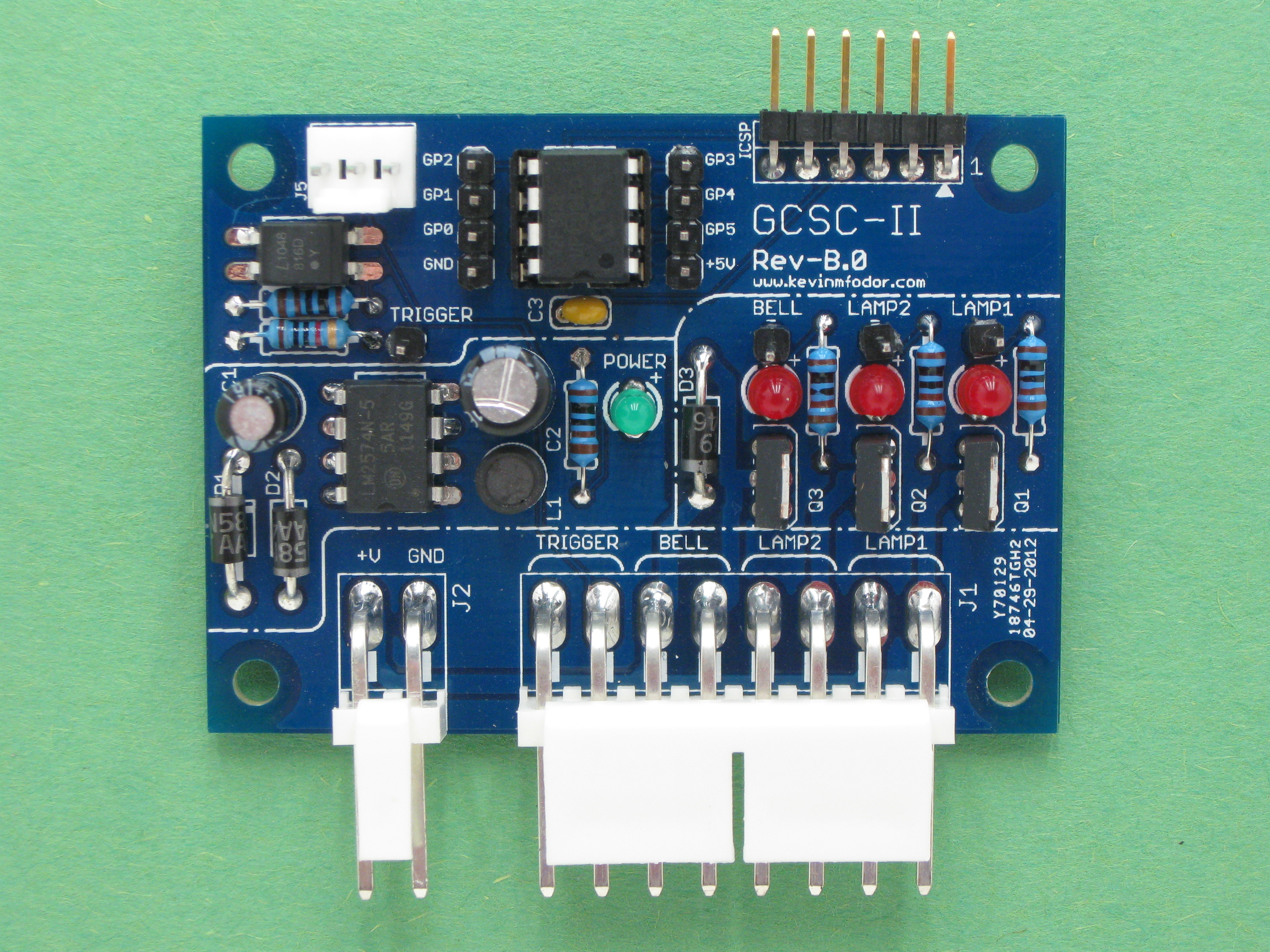
This project guide explains how to build an operating railroad grade crossing signal controller (GCSC) for controlling a simulated railroad crossing signal that has working flashing lamps and striking bell. Just like the real thing!
This board was also designed with hacking in mind. Due to the on-board 5 VDC power supply and extensive breakout headers and detailed silkscreening it also makes an excellent Microchip PIC12 development board. The I/O pins used for the GCSC-II implementation can be detached though small cut-trace pads on the back of the board so that you can route the micro’s I/O pins to anywhere you like. Separately the opto-isolated input and 3 high-power outputs can be re-purposed for many other projects and experiments. You can even try connecting them to your own bread board for off-board development.
All of the design and documentation for this project is maintained on a GoogleCode project site which you can find at this link: http://code.google.com/p/gcsc-ii/
There you will find the gerbers, complete parts lists and detailed design documentation for this board. Also feel free to contribute further on that site.
Along with my Blog post, this video shows one example of what can be done with this controller.
I hope you enjoy building and hacking this board as much as I did designing it. If you have done something with it and found it helpful, drop me a line. I would love to hear about it.


