On December 21st, 1968, exactly 55 years ago today, NASA sent humans outside of low earth orbit for the first time, captivating the world and ushering in a new era of space travel. An estimated 400,000 engineers, scientists, and manufacturers worldwide are accredited for helping build the rocket. 

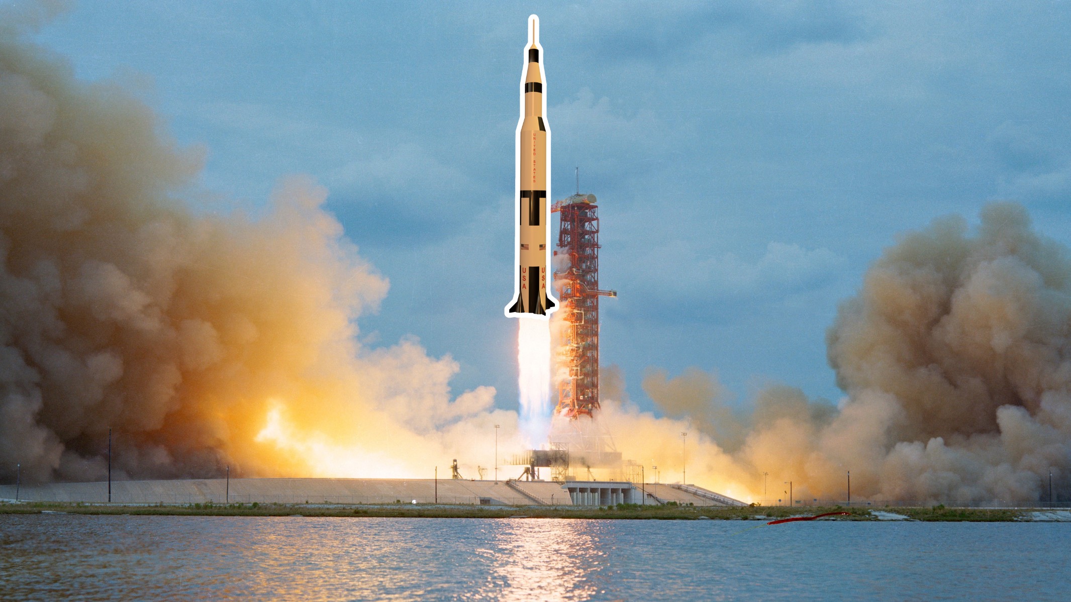
To commemorate this milestone, we will model the Saturn V rocket responsible for the journey at 1/180th of the original scale. The design can be exported and viewed in augmented reality and saved as an STL for 3D printing (or you can skip the process and download a completed version here). The bottom cavity will fit a model rocket engine if you want to 3D print and launch one! 

YouTube player

We will use Fusion360 for this build, but you are welcome to use the dimensions and build in your CAD program of choice.

As the broadcaster of Apollo 8 said in 1968, “And we have liftoff!”

YouTube player

Project Steps

1

Change the units to millimeters by expanding the Document Settings, hovering your mouse over the Units, and clicking on the pop-up Change Active Units. Set them to mm.

2

Expand the Create pulldown and click on the Create Sketch tool in the top left corner.

3

Click on the Top plane, which intersects with the green and red axes. You will be building this rocket from the bottom up.

4

Type C for circle, click on the origin, move your cursor away, and click again to define the first circle. Do the same operation to make the second circle.

Type D for dimension, click on one of the circles, pull your cursor away, click again, type 54, and press enter. This will define one circle as having a diameter of 54 mm. 

Repeat this operation for the other circle but set it to 29 mm. This inner hole allows you to fit a hobby rocket motor in it.

5

Click the Finish Sketch (Green Checkmark) button in the top right corner. Move your cursor to the view cube in the top right corner, and click on the house icon to get a 3D view of your sketch.

6

Type E for extrude, click on the ring in the sketch and set it to a distance of 360 mm. Click OK.

7

The default material in Fusion 360 is gray steel which does not look like the Saturn V rocket. Let’s change this to resemble the actual rocket.

Press A for appearance, and type “white paint” in the search bar. Click and drag one of the options onto the cylinder to change its color. Click OK.

8

Create a new sketch on the top of this tube by clicking New Sketch and selecting the flat ring surface. This will give you a top-down view.

Type P for project, click on the ring, and click OK. This should turn the two circular edges purple. This allows us to click on the top ring and middle circle on this layer. Click Finish Sketch.

9

Press E for extrude. Click on the ring and the inner circle and pull the blue arrow upwards 30 mm. You can also type 30 mm into Distance.

Notice the ring icon above the arrow. This adjusts the taper of the extrusion. Set the taper angle to -16 degrees. Click OK.

10

The building blocks of this project will be a series of cylinders and tapered cylinders stacked on top of each other. Both can be made using the extrusion tool. 

The nice thing about the extrusion tool is that you can extrude any flat face without making a sketch every time. 

Type E for extrude, click on the top of the tapered cylinder, and type 70 mm. Click OK.

11

Type E for extrude, click the top of the previous cylinder, and set it to 44 mm tall with a -9.4 degree taper. Click OK.

12

The following four extrusions will be:

Extrusion 5: 28 mm

Extrusion 6: 15 mm, -30.7 degree taper

Extrusion 7: 50 mm

Extrusion 8: 4 mm, -25 degree taper

13

With the main body done, you can work on the four thrusters and fins at the bottom of the rocket. Because they are equally spaced around the bottom, you can use a new tool called circular pattern, saving time, as you only need to make one thruster and one fin. 

To make the cone-shaped thrusters, you will start by sketching a circle on the bottom face of the rocket and extruding it through the body with a taper.

14

Make a new sketch and click on the bottom of the body. Type C for circle and make one to the right of the origin, away from the rocket.

15

Click on the Horizontal/Vertical constraint tool in the middle of the toolbar and click on the origin and the center of the circle. This will prevent it from moving up and down.

16

Use the coincident constraint and click on the circle’s center and the outer circle’s circumference.

17

Finally, use the tangent constraint and click on the circle’s circumference and then the inner circle of the base. Click Finish Sketch. 

18

Type E for extrude. Click on the two profiles that make up the circle and orbit your view to the top side of the rocket. Extrude the two profiles 45 mm upwards and -16 degrees of taper. Because you are making something that interferes with another existing body, the cone will be red. Change the Operation from Cut to Join at the bottom of the dialog box. Click OK.

19

To make the fin, make a new sketch on the Front plane. Type L for the line tool and make the shape in the picture. Hit Esc to get rid of the line tool. 

Select the coincident constraint and click the bottom horizontal line and origin, defining it and turning it black. This tool draws an imaginary line that intersects to a point, the origin in this case.

20

Type D for the dimension tool and give it the dimensions shown. The shape should turn black and have a pale light blue filling, meaning it is fully enclosed. Click Finish Sketch.

21

Type E for extrude and click on the new profile you sketched. Change the Direction to Symmetric. 

Change the Measurement from Half Length to Whole Length and set it as 2 mm. Click OK.

22

Now you have one thruster and one fin and will use the circular pattern tool to make three more. 

Expand the Create pulldown and go Pattern >> Circular Pattern.

23

Change the Object Type to Features and click on the two most recent extrusions in the timeline. The timeline is in the bottom left of your screen. Extrusions are represented by blue blocks with an up arrow. Click on Axis, select the blue Z axis, change the Quantity from 3 to 4, and click OK.

Conclusion

Done! This replica is now ready to be exported for 3D printing and augmented reality.


To export this as an augmented reality model, navigate to File >> Export >> and change the file type to .USDZ. Save this file to a cloud account of your choosing (like iCloud Files, an AR viewer app, or Google Drive), so you can open it up on your smartphone. 

If you are using iOS, save the file to your  Files directory, and open it. Move your camera over a tabletop, and it should appear. You can move your camera to look at details or double-finger pinch to scale it up or down. Magic!  


To export this file as an STL for 3D printing, navigate to File >> Export and select STL. You are now ready to import this file into your slicer program or send it to a company to make it for you. 


If you feel energized by this process, consider using other tools inside of Fusion to customize your rocket and make it look even better. In the interest of keeping this short, this is outside the scope of this tutorial, but we do go more in-depth at www.cadclass.org.


Jake Sugden and Joshua Manley are the cofounders of CADClass, an online Fusion360 CAD program helping makers and future makers bring their creativity to life. If you enjoyed this tutorial, would like to learn more, or simply want to connect, they can be reached at create@cadclass.org