


When touchscreens first came on the scene I was, like everyone, excited for the future of user interfaces. What wound up happening is horrible.
Instead of getting the exacting control depicted in science fiction, we received abstruse devices that don’t make it clear whether a program (“app”) is open or closed, which force us into a world of childishly colorful windows that give no quarter in the battle for precision, and which are used to maintain a culture of hyperconnectivity.

It felt like the whole world went from using emails and telephones to expecting texting in the blink of an eye, and I found myself hardened to reject it all. I stuck with a flip phone, and with the exception of a month-long experiment with a smartphone, have been happy to have only basic phone functionality and a good excuse not to text, because everyone knows how awkward texting would be on a flip phone. But even the flip phone isn’t immune to stupid user interface design.
I’d been itching for years to use a rotary dial as a data entry interface for some project. They’re easy to interface with electrically, so I imagined a rotary numpad replacement for a computer, or perhaps as a means to enter sky coordinates on a steampunk telescope mount. But when I noticed the Adafruit Fona, the possibility of building a cell phone seemed almost easy, and adding a rotary dial seemed just quirky enough to be fun. I could finally have a phone that would behave the way I want it to. It could be entirely mine and as tactile as I could imagine, and I could just not write the firmware (Arduino sketch) needed to allow texting. The point wouldn’t be to have something wacky, but to have to be a real, usable phone that I would want to use as my primary phone; a demonstration of a phone that goes as far from having a touchscreen as possible while being a “slap in the face” to smartphones, because in a few ways it would actually be more functional.
It would have a real external antenna with superior reception. It would have dedicated physical keys for the one or two people I call most, and voicemail. It would have instantaneous signal strength and battery metering with more resolution than just four or five bars. It would have an e-paper display — an entirely underused technology that’s bistatic, meaning it doesn’t take energy to display a fixed message and is absolutely beautiful. The power switch would be an actual slide switch that doesn’t require holding down a stupid button that makes you guess about what it’s really doing. But most importantly, I would have control. If I wanted to change something about the phone’s behavior I would just do it, and if there was something I don’t like there would be no one to blame but myself.
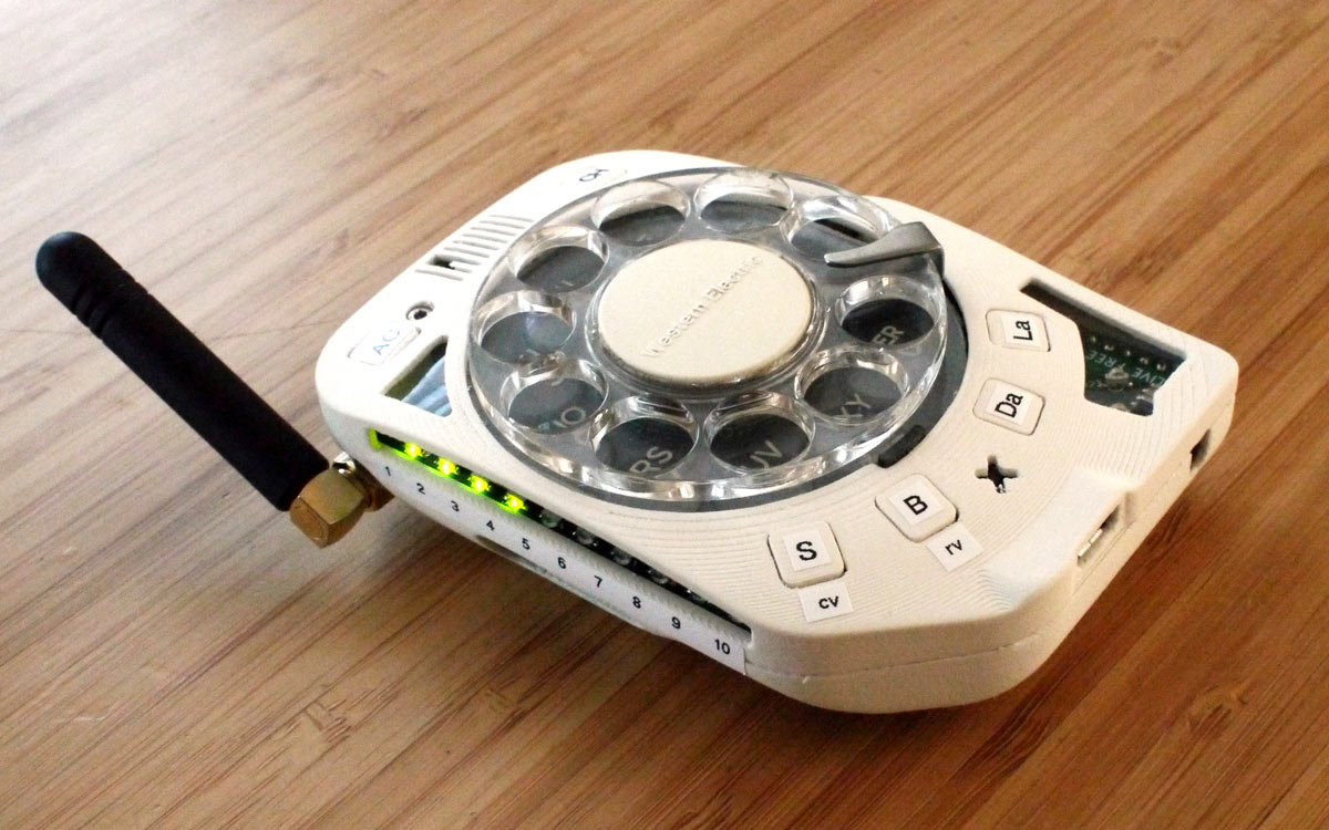
The finished phone fits in a pocket. It’s reasonably compact. Calling the people I most often call is faster than with my old phone, and the battery lasts more than a day. It is now, in fact, my primary phone.
Additional information available at skysedge.com/unsmartphones/rotarycellphone_3g/build. Here’s an overview of putting one together.
Materials
- Rotary cellphone main circuit board Make it from the KiCad design files or send them to a PCB maker like pcbway.com. I’ve also made it available as a kit from skysedge.com.
- Rotary dial, Western Electric model 10A
- Adafruit Fona 3G cellular breakout board American or European version, depending where you live, Adafruit #2687 or 2691
- Compatible 3G SIM card I use AT&T prepaid.
- Adafruit eInk Breakout Friend #4224
- ePaper display, 2.13″ flexible Good Display #GDEW0213I5F, Adafruit #4243
- Battery, 1.2Ah LiPo with JST connector such as Adafruit #258
- Antenna, quad-band GSM with SMA connector Adafruit #1858
- SMA bulkhead connector w/µFL pigtail Adafruit #851
- 3D printed enclosure and buttons
- Labels
- Clear plastic packaging material to be cut into “windows” for enclosure
- Threaded inserts, M2, heat-set McMaster-Carr #94180A307
- Machine screws, M2, socket head: 6mm (2), 10mm (3), and 14mm (1)
- 3M 468P transfer adhesive
- Tape, Scotch double-sided
- Epoxy or plastic model glue
Tools
- Soldering station with fine chisel tip
- Solder, fine-gauge e.g. 0.20″
- Solder flux
- Tweezers, fine
- Tweezers, coarse or small needlenose pliers
- Hex keys aka Allen wrenches
- Scissors
- Hot glue gun
Assemble the PCB
-

Figure A -

Figure B -

-
Figure C


The heart of the phone is a custom 4-layer PCB. I made both the electrical design and board layout in KiCad, a fantastic open source electrical design suite that puts some commercial EDA software to shame (Figures A and B).
I sent the design files to a PCB “board house” for manufacture. With the company I use, a batch of 5 PCBs comes out to about $60 delivered. I did all the soldering by hand. Most of the components are surface-mounted, which might scare people, but with a good soldering station, tweezers, and some patience, this is a doable hand-solder job. As it’s a double-sided board, expect to spend a long afternoon working on it. You’ll also need to solder on an Adafruit ePaper Breakout Friend, which provides control for the e-paper display, and solder a header to the Adafruit Fona 3G, which is our cell radio daughterboard (Figure C).
Upload the Software
With the board together you can flash the firmware (i.e. upload the Arduino sketch). This will require a few extra libraries loaded into the Arduino IDE, like Jean-Marc Zingg’s GxEPD library for controlling the e-paper display, a Fona library from Adafruit, a couple other libraries, and the MegaCore board support add-on from MCUdude which will allow the Arduino IDE to work with the ATmega2560V microcontroller.
I always use an in-system programmer when uploading Arduino sketches. Instead of dealing with the USB port, which can be flaky for this purpose, an AVR-ISP-Mk2 programmer can be used instead and this always just works for uploading firmware. They go for about $20 at Digi-Key and Mouser and plug into the ICSP header which is always present on Arduino-like boards (in case you didn’t know what it was for), and then, to initiate the upload we just press Ctrl+Shift+U within the Arduino IDE. No need to select the USB device assignment. The board settings within the Arduino IDE should be as follows:
Board: ATmega2560, Clock: External 8MHz, BOD: BOD 2.7v, Compiler LTO: LTO enabled, Pinout: Arduino MEGA pinout, Bootloader: Yes (UART0).
Build the Mechanicals and Enclosure
-

Figure D -


The specific rotary dial needed is a Western Electric model 10A (Figure D). This model comes in many sub-variants, but as long as it’s some kind of 10A it should work. These can be found as part of certain Trimline rotary telephones (check eBay) or from specialty suppliers of old phone parts. I have more notes at skysedge.com/unsmartphones/rotarycellphone_3g/build/dials.
You’ll need to modify the dial to fit the PCB and 3D printed enclosure properly, which involves hacking off the metal mounting tabs around the dial’s perimeter, filing, and cutting down the potted mounting feature for the dial’s reed switch. Depending on the specific variant, it may also be necessary to remove the electrical leads for the reed switch in the process of cutting it, and then solder them back on afterwards. Once the dial passes a test-fit with the PCB and the enclosure (Figure E), screw the dial onto the PCB and check that using it activates the LEDs on the board when the board is energized.
-
Figure E -
Figure F


3D print the enclosure and buttons; the STL files are available on my site. Press the M2 heat-set threaded inserts into place using a soldering iron (Figure F).
The SMA to μFL adapter cable can be installed into the backside of the enclosure, and as an optional step you can add clear plastic “windows” to the cutouts in the enclosure which provide visibility to certain parts of the board while also protecting against lint ingress. I use product packaging from the garbage for this.
Flexible e-Paper
Next comes the trickiest part of the whole process: bonding the flexible e-paper display. While marketed as flexible displays, these are fragile. I killed about six of them in the process of understanding their limitations and figuring out how best to bond them to the enclosure.
-

Figure G -
Figure H


The flex cable is resilient and can be folded on itself, but the section between the flex cable and the white portion of the display is extremely delicate, as it contains an encapsulated integrated circuit which is not strain relieved. You can actually see the silicon below the top surface of the kapton. Bending it in the “wrong” direction of the display will snap it in two. Bending in the “correct” direction will disrupt whatever bonding is done between silicon and the traces in the kapton flex material and cause display artifacts or complete failure. So keep this portion as flat as possible; I’ve found that the best thing is to epoxy it to a flat segment of the enclosure, or perhaps to use transfer adhesive (Figures G and H).
Much effort also went into designing the bend around the back of the display to be as tight as it can be without causing display glitches, and it’s not clear that I’ve gone far enough in this regard.
Close It Up

The buttons can now be set into the enclosure and the main board lowered into place. Before doing this, you want to have a compatible SIM card installed in the Fona (AT&T prepaid works for me in the U.S.), and of course the Fona should be inserted into the socket on the main board. Some care should be taken to be sure cables for the LiPo battery and the SMA connector are routed well and that the battery is nestled next to the Fona so that the back of the enclosure will fit, and there’s a tricky process involved in mating the FPC connector to the eInk Friend daughterboard.
With the main board installed and the rotary dial sticking out the other side of the enclosure, we can install the back of the enclosure and finish bonding the e-paper display in place, this time using simple double-sided tape, which permits you to remove the display again without damaging it if you need to open the phone for maintenance.
Assuming the recommended SMA duck-style antenna is used, after attaching the antenna another small piece gets screwed on over the nut-section of the SMA connector. I call this the “SMA plug” and it retains the SMA nut to be fixed in a slightly loosened position that allows the antenna to swivel, even though it isn’t designed for articulation. The joint on an actual articulating antenna takes up enough space that I felt the need to work out this hack on a more compact “fixed” SMA antenna, and it works quite well.
The only remaining detail would be to decorate it with labels for the buttons and switches, as desired. I use an Epson LabelWorks label maker with either black or white ink on clear backing, depending on what color casing I’ve 3D printed. The labels need to be cut down to size with scissors, and to get them to stick well to the ridges/steps in the 3D printed plastic it’s helpful to put down a small blob of glue to fill the gaps arising from the steps from the 3D printing. Plastic model glue has worked well but there are likely even better options.
A working rotary-dial cell phone should now be sitting before you. Cool.


